
Cutting tool

a cutting tool and metal technology, applied in the field of metal cutting tools, can solve the problems of unavoidable circumstances of cutting processing under heavy-duty cutting conditions, such as greater cutting depth and faster feeding, and easy chipping in the hard coating layer, and achieves superior wear resistance and cutting performance, superior mechanical and thermal shock resistance, and high cutting performance.

Active Publication Date: 2007-04-10
MITSUBISHI MATERIALS CORP
View PDF21 Cites 26 Cited by
  • Summary
  • Abstract
  • Description
  • Claims
  • Application Information

AI Technical Summary

Benefits of technology

[0019](2) An α-Al2O3 layer formed by vapor deposition on the heat-treated Al2O3 core thin film has significantly improved strength as compared with a conventional α-Al2O3 layer. Thus, a coated Cermet cutting tool in which a hard coating layer was formed by vapor deposition as the upper layer was confirmed to demonstrate superior chipping resistance as compared with a conventional Cermet cutting tool in which a conventional α-Al2O3 layer was formed by vapor deposition.
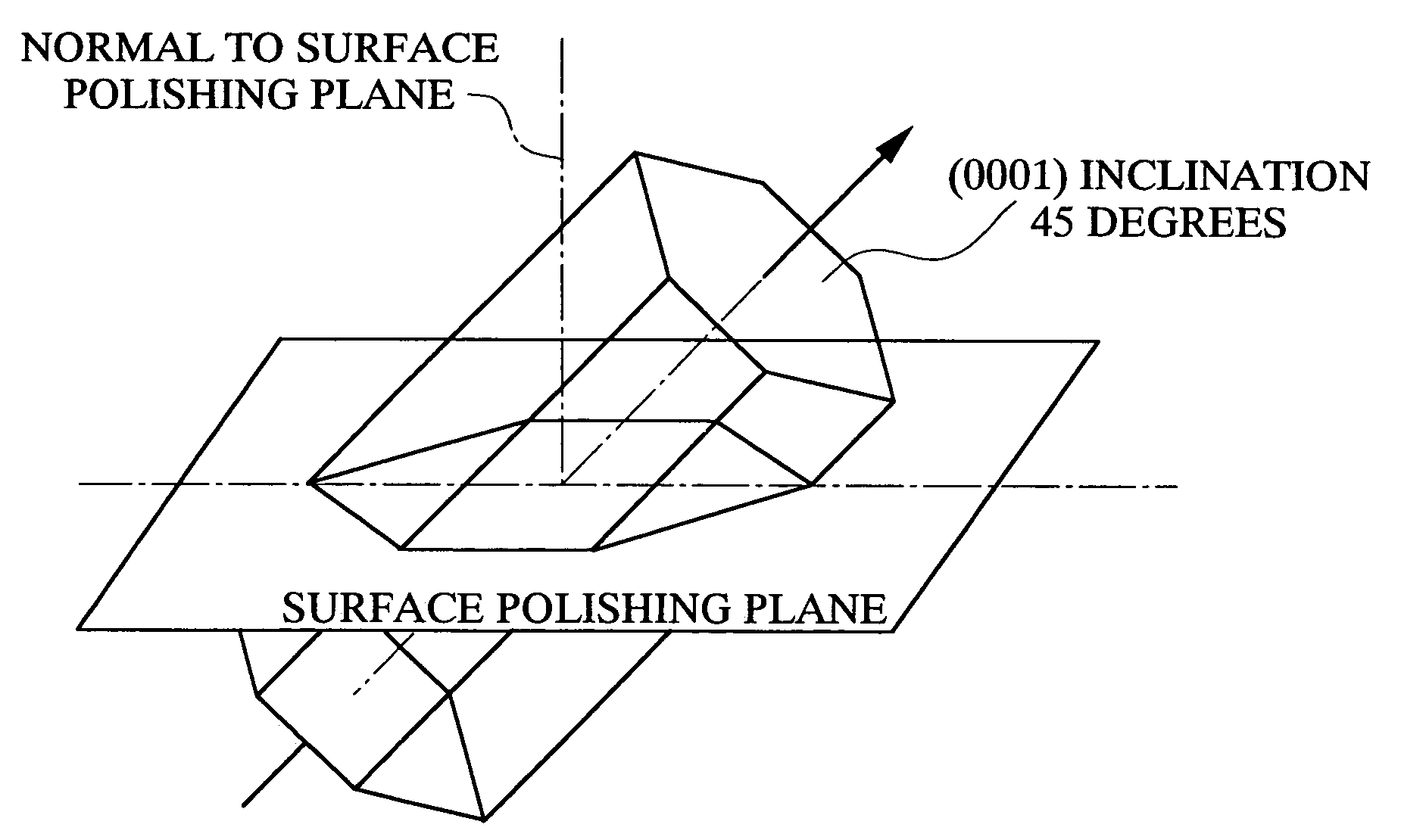
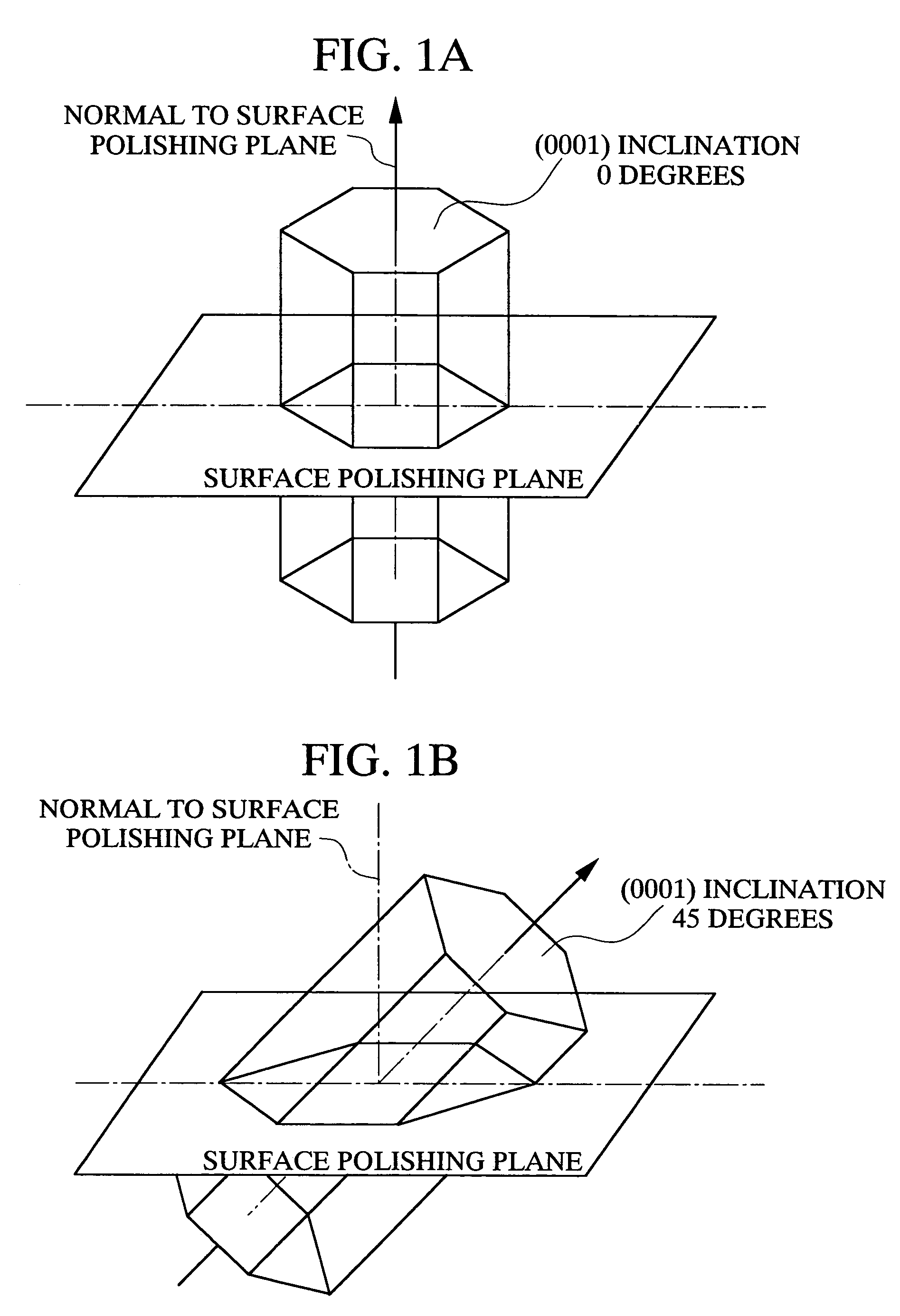
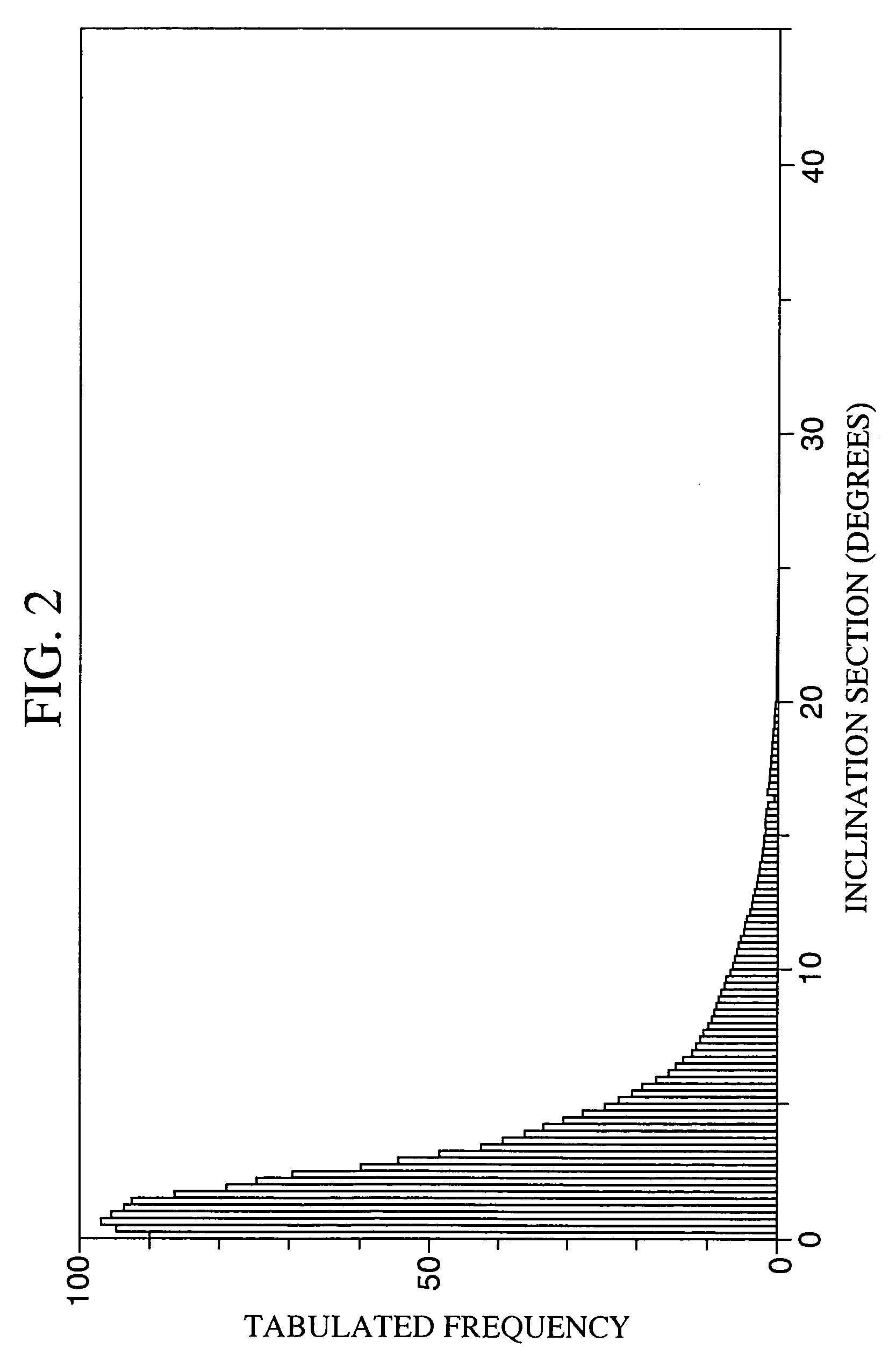
[0023]In the cutting tool of the present invention, the α-Al2O3 layer, which composes the hard coating layer, exhibits a pole plot graph in which the highest peak appears in the inclination section within a range of 0–10 degrees as shown in FIG. 2, and demonstrates superior chipping resistance. Thus, the cutting tool of the present invention exhibits superior wear resistance and cutting performance over a long period of time even during high-speed intermittent cutting of various types of steel and cast iron that is accompanied by extremely high levels of mechanical and thermal shock as well as the generation of a large amount of heat.

Problems solved by technology

Accompanying these needs, the speed of cutting processing is tending to become even faster, resulting in the unavoidable circumstances of cutting processing under heavy-duty cutting conditions including greater cutting depth and faster feeding.
However, although the α-Al2O3 layer that composes the hard coating layer has superior heat resistance, since it is not provided with adequate strength, when used for high-speed intermittent cutting under severe cutting conditions, namely high-speed intermittent cutting in which thermal shock is repeatedly applied at an extremely short pitch to the cutting edge, chipping occurs easily in the hard coating layer.
As a result, the cutting tool reaches the end of its service life in a comparatively short period of time.

Method used


Image

  • Cutting tool
  • Cutting tool
  • Cutting tool

Examples


examples

[0037]The following provides a more detailed explanation of the cutting tool of the present invention by referring to Examples and Comparative Examples.

[0038]As raw material powders, WC powder, TiC powder, ZrC powder, VC powder, TaC powder, NbC powder, Cr3C2 powder, TiN powder, TaN powder and Co powder having a mean particle diameter of 1–3 μm were prepared. These raw material powders were blended to the blending compositions shown in Table 1, wax was added to them, and they were then mixed using a ball mill for 24 hours in acetone. After drying under reduced pressure, the dried mixtures were pressed formed into green compacts of a predetermined shape at a pressure of 98 MPa. Next, the green compacts were vacuum sintered for 1 hour in a vacuum at 5 Pa at a predetermined temperature within the range of 1370–1470° C. After sintering, the cutting edges were subjected to honing of R=0.07 mm to produce tool bases A through F made of WC-based cemented carbide having the indexable insert s...


PUM

PropertyMeasurementUnit
thicknessaaaaaaaaaa
thicknessaaaaaaaaaa
thicknessaaaaaaaaaa

Abstract

The present invention provides a cutting tool in which the hard coating layer demonstrates superior chipping resistance. The cutting tool has a tool base composed with tungsten carbide-based cemented carbide or titanium carbonitride-based Cermet, and a hard coating layer provided on the surface thereof; wherein the hard coating layer includes: (a) a Ti compound and / or Zr compound layer, which is a lower layer, comprising one or more layers of a TiC layer, TiN layer, TiCN layer, TiCO layer, TiCNO layer, ZrC layer, ZrN layer, ZrCN layer, ZrCO layer, ZrCNO layer and (b) an aluminum oxide layer having an α crystal structure which is an upper layer, including the highest peak in the inclination section within a range of 0–10.

Description

BACKGROUND OF THE INVENTION[0001]1. Incorporation by Reference[0002]The present application claims priority under 35 U.S.C. §119 to Japanese Patent Application Nos. 2003-053059 filed on Feb. 28, 2003 and 2003-056639 filed on Mar. 4, 2003. The contents of the applications are incorporated herein by reference in their entirety.[0003]2. Field of the Invention[0004]The present invention relates to a Cermet cutting tool having a coated surface (to be referred to as a coated Cermet cutting tool) used for high-speed, intermittent cutting of various types of steel, cast iron and so forth, and its hard coating layer in particular demonstrates superior chipping resistance.[0005]3. Description of the Related Art[0006]Known examples of coated Cermet cutting tools comprise a base (to be generically referred to as the tool base) made of tungsten carbide (WC)-based cemented carbide or titanium carbide (TiC)-based Cermet, and a hard coating layer. This hard coating layer comprises:[0007](a) a Ti co...

Claims


Application Information

Patent Timeline
Patent Type & Authority Patents(United States)
IPC IPC(8): B23P15/28B23C5/16C23C16/02C23C16/30C23C16/34C23C16/36C23C16/40C23C28/04C23C30/00
CPCC23C16/0272C23C16/30C23C16/34C23C16/36C23C16/403C23C30/005C23C28/042C23C28/044C23C30/00B23B2228/10Y10T428/30Y10T428/265Y10T428/24975F16B2/065F16B5/0685F16L3/1016
Inventor OSHIKA, TAKATOSHIUEDA, TOSHIAKIHAYAHI, TAKUYA
Owner MITSUBISHI MATERIALS CORP
Learn More