Optical assembly and method for detection of light transmission

a technology of optical assembly and light transmission, applied in the field of optical assembly, can solve the problems of limited application of fluorescence detection, limited detection range of absorbance detection, and limited application of absorbance detection, and achieve the effect of improving separation

Active Publication Date: 2007-08-28
PARAYTEC
View PDF8 Cites 31 Cited by
  • Summary
  • Abstract
  • Description
  • Claims
  • Application Information

AI Technical Summary

Benefits of technology

[0071]Vessels may have any desired separation, suitably are fused or adjacent or are spaced apart. A lower separation increases packing density but a higher separation reduces intervessel interference, in particular optical interference. It is a particular advantage of the invention that intervessel spacing may be used. This is not possible in the embodiment of Yeung et al above, for example which needs minimal vessel separation to minimize stray light.
[0072]The vessel may be of suitable length and depth according to the desired use. Preferably for capillaries or channels length is in the range 2 cm-2 m for example in the range 2.5-6 cm for microfabricated channels or 6-100 cm length for capillaries, more preferably 10 to 60 cm. Greater length allows application of higher voltage in capillary electrophoresis and improved separation. For microtitre plate well, preferable inter-vessel center to center spacings are compatible with standard microtitre plate formats, such as 2.25, 4.5 and 9 mm.
[0073]Preferably a vessel is of 3 μm to 20 mm in depth or internal diameter, and 4 μm to 30 mm in external diameter, more preferably 9 μm-3 mm in depth or internal diameter and 10 μm to 3.5 mm in external diameter, more preferably 10-380 μm, most preferably less than or equal to 200 μm in depth or internal diameter or external diameter. A vessel wall is importantly of suitable thickness for the optical properties of the invention. This is particularly relevant for vessels of small internal diameters. Accordingly vessel internal diameter or “bore” may be selected and vessel wall material selected, and suitable outer diameter determined accordingly to give the required optical properties. For silica capillaries with internal diameter (hereinafter i.d.) in the range 20 to 250 μm, for example 20, 25, 50, 75 or 100 μm, external diameters (hereinafter o.d.) is preferably in the range 100 to 380 μm, for

Problems solved by technology

Fluorescence detection is limited in its application since only a limited number of molecules are naturally fluorescent and many have to be derivatized in reproducible and quantitative manner.
However a limitation of absorbance detection lies in the operable wavelength of detection.
However many common solvents absorb significant amounts of light at wavelengths below ˜200 nm, and the resulting solvent absorption signal distorts and masks signals resulting from the substrate to be detected.
Moreover a fundamental limitation of single point absorbance detection is the impossibility of creating an image of the source at the detection point on capillary that is brighter than the light source.
Such a system becomes more complex once a parallel capillary array is introduced in place of the single capillary.
Optics to focus light on the core of each capillary would be extremely complex and therefore irradiating both the core and walls of each capillary becomes a practical consequence.

Method used


Image

  • Optical assembly and method for detection of light transmission
  • Optical assembly and method for detection of light transmission
  • Optical assembly and method for detection of light transmission

Examples


example 1

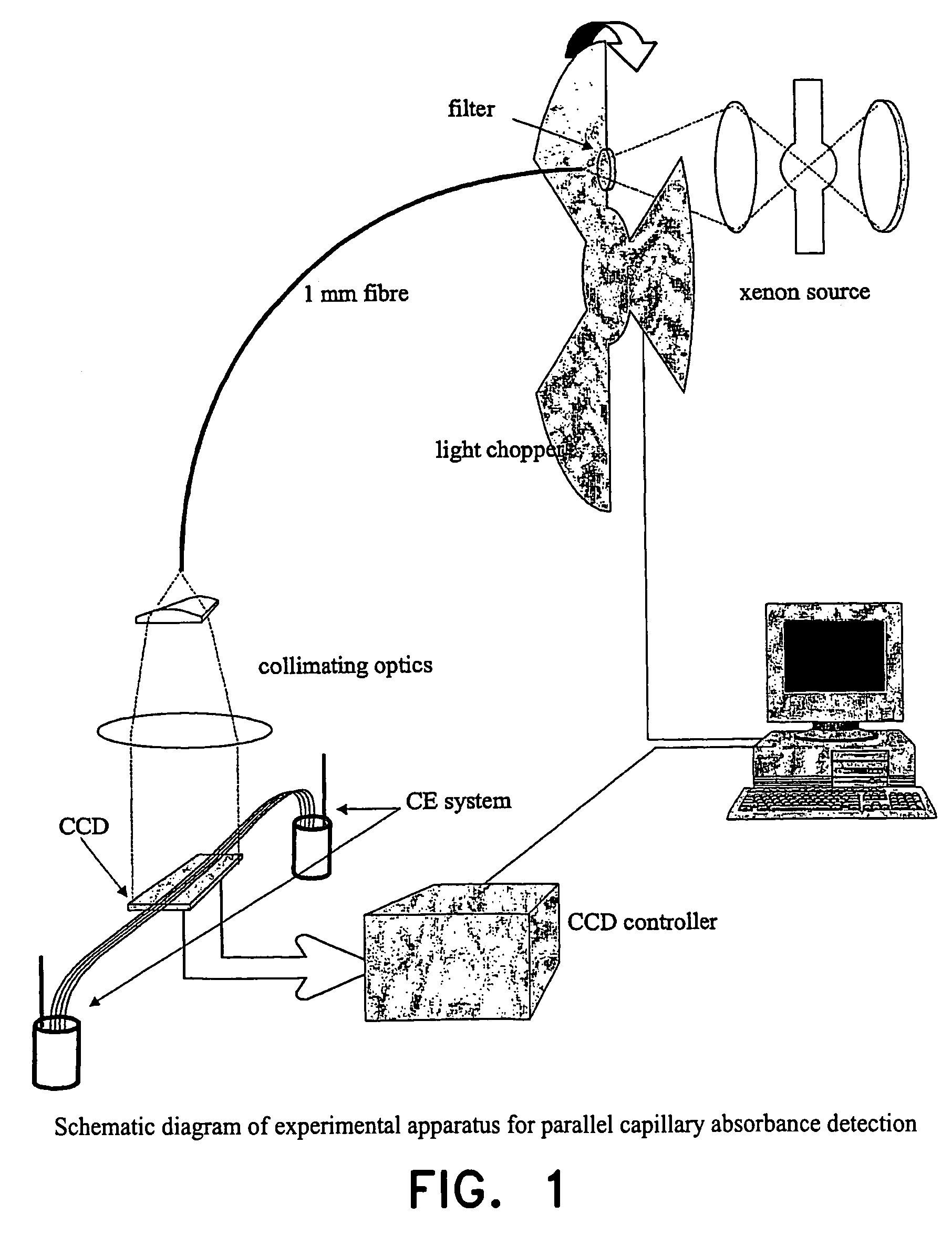
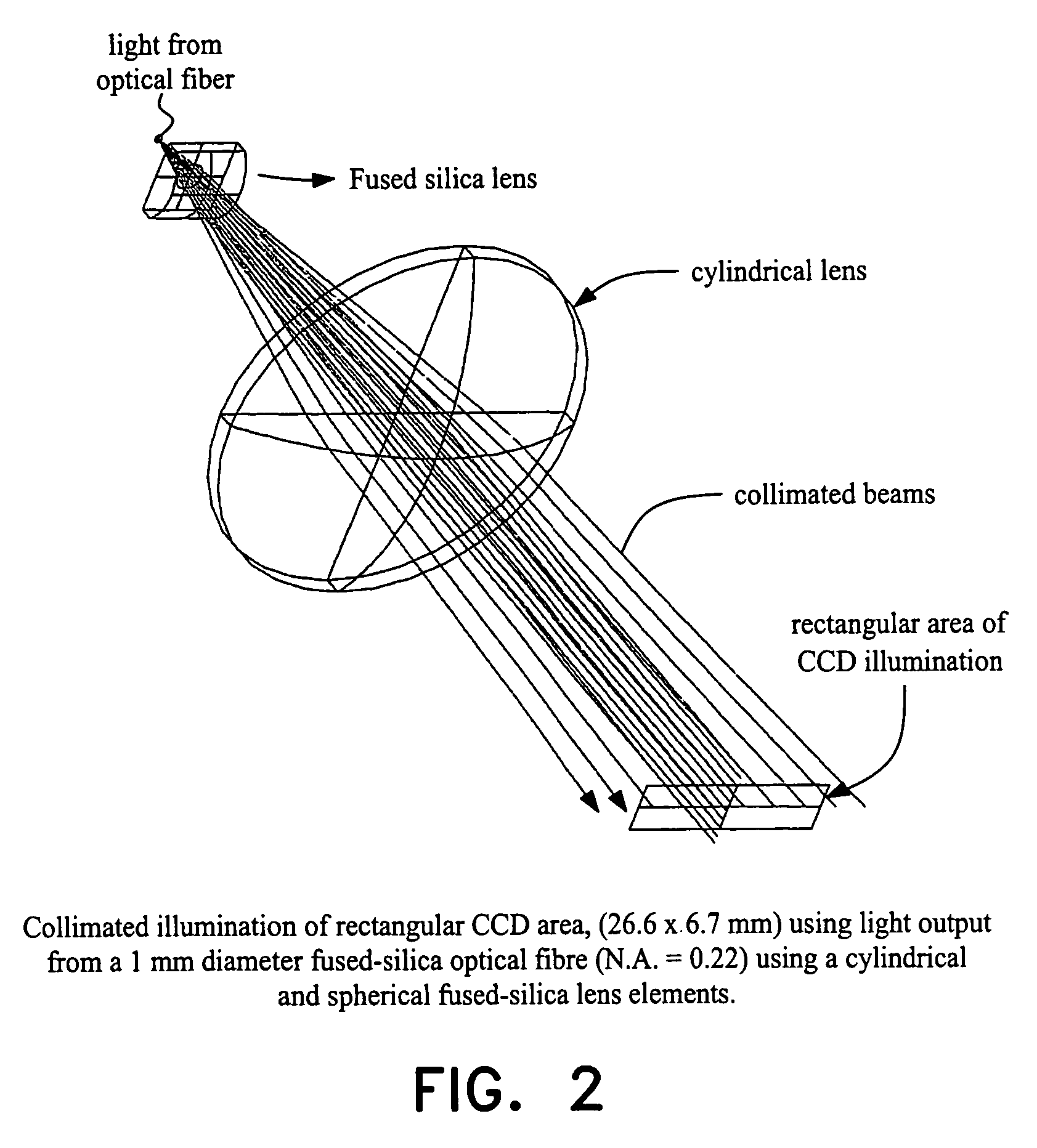
[0122]The experimental setup is shown in FIG. 1. The output from a 75 W xenon lamp is launched into a single 1 mm diameter fused silica fiber. The light output from the fiber is shaped and collimated using cylindrical and spherical fused silica lens elements (FIG. 2) to illuminate the rectangular area of the CCD. The CCD chip used is EEV CCD 30-11 and is thermostatted and controlled by a system designed and built by York Electronics Center; it has 1024 by 256 active pixels, each 26 μm square, with a total active area of 6.7×26.6 mm. The CCD chip has a fiber optic stud (faceplate) that protects the CCD surface. The fiber optic stud is not UV transparent, so a UV phosphor is coated onto the surface of stud to make the detector sensitive to a wide wavelength range from NIR to below 200 nm. The charge accumulated on the CCD is read out in a series of snapshots; to prevent image smearing a light chopper ensures that the CCD is not illuminated during the readout period. An exposure rate o...

example 2

[0133]

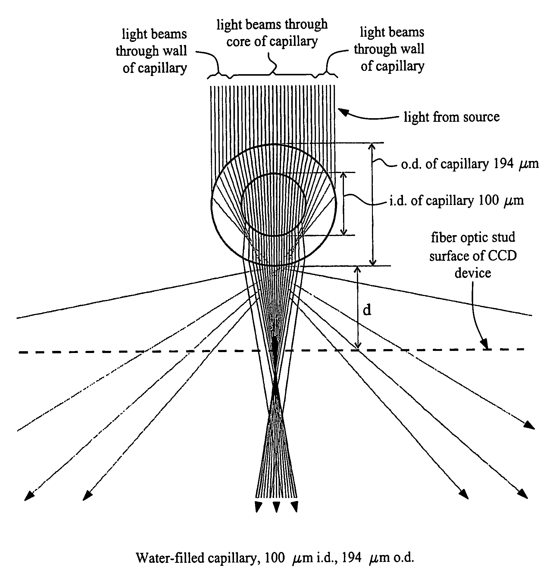
TABLE 1Table showing, for vessel with circular outer and inner crosssections, minimum values of ratio of the outer wall to detector distance dand the outer diameter of the vessel o.d. (d / o.d.) in order to obtain spatialseparation between core and wall beams. Values are shown as a functionof ratio of inner and outer diameters of the vessel (i.d. / o.d.) for a rangeof solvents and vessel materials. Entries x indicate no spatialseparation possible.i.d. / o.d.i.d. / o.d.i.d. / o.d.i.d. / o.d.0.200.250.330.50Water / silicax2.01.00.5Hexane / silica1.61.00.60.4Dichloromethane / silica0.60.50.40.2Water / polycarbonatexx2.10.5Water / flexible clear0.50.50.50.4tubing (Tygon chemfluor367)

[0134]Values of refractive indices used in ray tracing analysis are: silica (1.458), water (1.333), hexane (1.375), dichloromethane (1.424), polycarbonate (1.585), Tygon chemfluor 367 (1.34). Other common reversed phase HPLC solvents, often used in admixture with water, are methanol (1.329) and acetonitrile (1.344): these a...

example 3

Feedback Control

[0136]An example of feedback control is the use in a CE experiment for stopping the sample in the detection window, by turning off the voltage when it is detected as having migrated to the center of the window (see FIG. 13). After stopping, the subsequent broadening of the sample peak due to diffusion is monitored as a function of time. Analysis of the change in peak variance with time enables the diffusion coefficient to be determined. The hydrodynamic radius of the sample molecule may then be calculated using Stokes law. Combination of the diffusion coefficient with the mobility, obtained from the time taken to reach the window under a given field strength, enables the charge on the analyte to be deduced. Any starting peak shape is acceptable, since convolution of the peak with a Gaussian enables the Gaussian component of the peak broadening to be extracted. Whilst the example shows peak broadening measured over a period of 30 minutes, data quality is such that dif...


PUM

PropertyMeasurementUnit
wavelengthaaaaaaaaaa

Abstract

An optical assembly comprising a light source, at least one sample vessel and a detector. The detector comprises a plurality of detector locations and the vessel comprises a wall and core of relative shape and dimensions adapted to contain a sample for detection and to define at least two spatially separated transmitted light paths, a first wall path which enters and exits the vessel walls only, spatially separated from a second core path which enters and exits the vessel walls and additionally the vessel core. The spatially separated wall and core paths are coupled to individual detector locations on the detector, a module or clip-on device therefor. Methods for detection and uses of the optical assembly are also disclosed.

Description

CROSS-REFERENCE TO RELATED APPLICATIONS[0001]This is a nationalization of PCT / GB03 / 003591 filed Aug. 15, 2003 and published in English.BACKGROUND OF THE INVENTION[0002]The present invention relates to an optical assembly comprising a sample vessel positioned in a direct light path between a light source and a light detector, in manner to enable transmission of light through the vessel; a method for detection of light transmission through sample contained within the vessel; an apparatus comprising the assembly; more particularly an apparatus for sample analysis for example for high throughput screening (HTS) or profiling or assays, such as enzyme assays; and uses thereof in the pharmaceutical, biomedical and bioscience, agrochemical, veterinary, materials and like fields, for detection, analysis, characterization and quantification or the like of samples contained in a vessel, and optionally further collecting separated components thereof; in particular in combinatorial chemistry; in...

Claims


Application Information

Patent Timeline
Patent Type & Authority Patents(United States)
IPC IPC(8): G01N21/00G01N1/10G01N21/01G01N21/03G01N21/05G01N21/59G01N27/447G01N30/46G01N30/74
CPCG01N21/0303G01N21/05G01N21/59G01N27/44721G01N30/74G01N30/466G01N2021/0346G01N2013/003
Inventor GOODALL, DAVID MURRAYBERGSTROM, EDMUND THOMASALLINSON, NIGEL MARTINMOON, KEVIN JAMES
Owner PARAYTEC
Why Eureka
Try Eureka