
Capacitive discharge plasma ion source

a plasma ionization and capacitive technology, applied in the field of gasdischarge ionizers, can solve the problems of limited ionization amount, limited utility of equipment using radioactive ionization sources, and limited use of equipment such as gas analyzers, among other equipment, to achieve the effect of preventing plasma wander, enhancing the stability of the discharge, and low power operation

Active Publication Date: 2007-09-25
DH TECH DEVMENT PTE
View PDF115 Cites 49 Cited by
  • Summary
  • Abstract
  • Description
  • Claims
  • Application Information

AI Technical Summary

Benefits of technology

[0007]RF discharge ionization reduces some of these disadvantageous effects. RF discharges are subdivided into inductive and capacitive discharges, differing in the way the discharge is produced.
[0008]Inductive methods are based on electromagnetic induction so that the created electric field is a vortex field with closed lines of force. Inductive methods are used for high-power discharges, such as for production of refractory materials, abrasive powders, and the like. In PCT publication number WO 01 / 69220, an inductively coupled plasma ionization technique is disclosed. Ions produced within the plasma source are provided to a high Field Asymmetric Waveform Ion Mobility Spectrometry (FAIMS) analyzer within a low pressure chamber of a mass spectrometer and in fluid communication with the plasma source for receiving ions therefore. The ions are separated in the FAIMS and at least some of the ions are provided to the mass spectrometer after separation. Inductively coupled ionization sources, such as described in WO 01 / 69220, tend to be power consuming, and further, the inductively coupled ionization sources are relatively complex, large and expensive.
[0009]Capacitive discharge methods are used to maintain RF discharges at moderate pressures p˜1-100 Torr and at low pressures p˜10−3-1 Torr. The plasma in them is weakly ionized and non-equilibrium, like that of a corona discharge. Moderate-pressure discharges have found application in laser technology to excite CO2 lasers, while low-pressure discharges are used for ion treatment of materials and in other plasma technologies. Varieties of radio-frequency capacitive discharge are discussed in Raizer, Shneider and Yatsenko, entitled Radio-Frequency Capacitive Discharges, © 1995 CRC Press LLC, with general background at pages 1-3.
[0010]In PCT publication number WO 96 / 19822, an RF ion source providing capacitively coupled ionization is described. The RF ion source is suitable for low power operation over a range of pressures in air. The source includes anode and cathode electrodes connected to an RF signal supply. The anode is adapted to provide a surface area over which a plasma discharge may occur. In this way, the anode presents no more useful surface than is required to accommodate the optimum area of the plasma discharge, preventing plasma wander and enhancing the stability of the discharge over known ion sources. The ion source provides an effective discharge with very low power even at atmospheric pressure.
[0011]Capacitively coupled ionization sources, such as described in WO 96 / 19822, are more efficient than inductively coupled ionization sources but may contaminate the sample due to electrode surface contact with the gas sample and plasma, leading to secondary ion emissions. The gas sample may corrode the electrode surface, and electrons freed from the plasma molecules, produced by the gas sample interaction with the electric field between the electrodes, can strike the electrode plates and are removed from the plasma, thus causing the plasma to have a net positive charge and an average potential relative to the plates. This drives the ions with a high velocity into the electrodes and can lead to the release of electrode plate molecules from the electrode surface. Also, the chemicals in the gas sample or plasma can chemically react with or corrode the electrodes, which can contaminate the sample. This can cause chemical analysis errors.
[0012]In view of the foregoing, there is a felt need for a clean and stable ionization source that is compact, light-weight and inexpensive and delivers a relatively high level of ionization energy for analytical applications in gas (e.g., air) at pressures including atmospheric pressure.

Problems solved by technology

However, because of their potential health hazard, wide-spread use of equipment using radioactive ionization sources in many applications has been limited.
Equipment such as gas analyzers, among other equipment, that uses radioactive sources are therefore limited in their utility.
While some smoke alarms use radioactive sources, the amount of ionization is low, and still requires government regulation.
Also these devices are typically delicate and fragile, and hence are generally not suitable to operate in harsh environments or in applications requiring a significant amount of manual handling.
Furthermore, UV devices require some maintenance and the intensity degrades overtime.
As such, even though photo-ionization and UV ionization devices are typically safer to operate than radioactive ionization sources, they are not a viable or cost-effective option in many circumstances, whether for general equipment use or for gas analyzers.
However, this process is not stable and often-times contaminates the sample, as would interfere with analytical results.
Inductively coupled ionization sources, such as described in WO 01 / 69220, tend to be power consuming, and further, the inductively coupled ionization sources are relatively complex, large and expensive.
Capacitively coupled ionization sources, such as described in WO 96 / 19822, are more efficient than inductively coupled ionization sources but may contaminate the sample due to electrode surface contact with the gas sample and plasma, leading to secondary ion emissions.
Also, the chemicals in the gas sample or plasma can chemically react with or corrode the electrodes, which can contaminate the sample.
This can cause chemical analysis errors.

Method used


Image

  • Capacitive discharge plasma ion source
  • Capacitive discharge plasma ion source
  • Capacitive discharge plasma ion source

Examples


Embodiment Construction

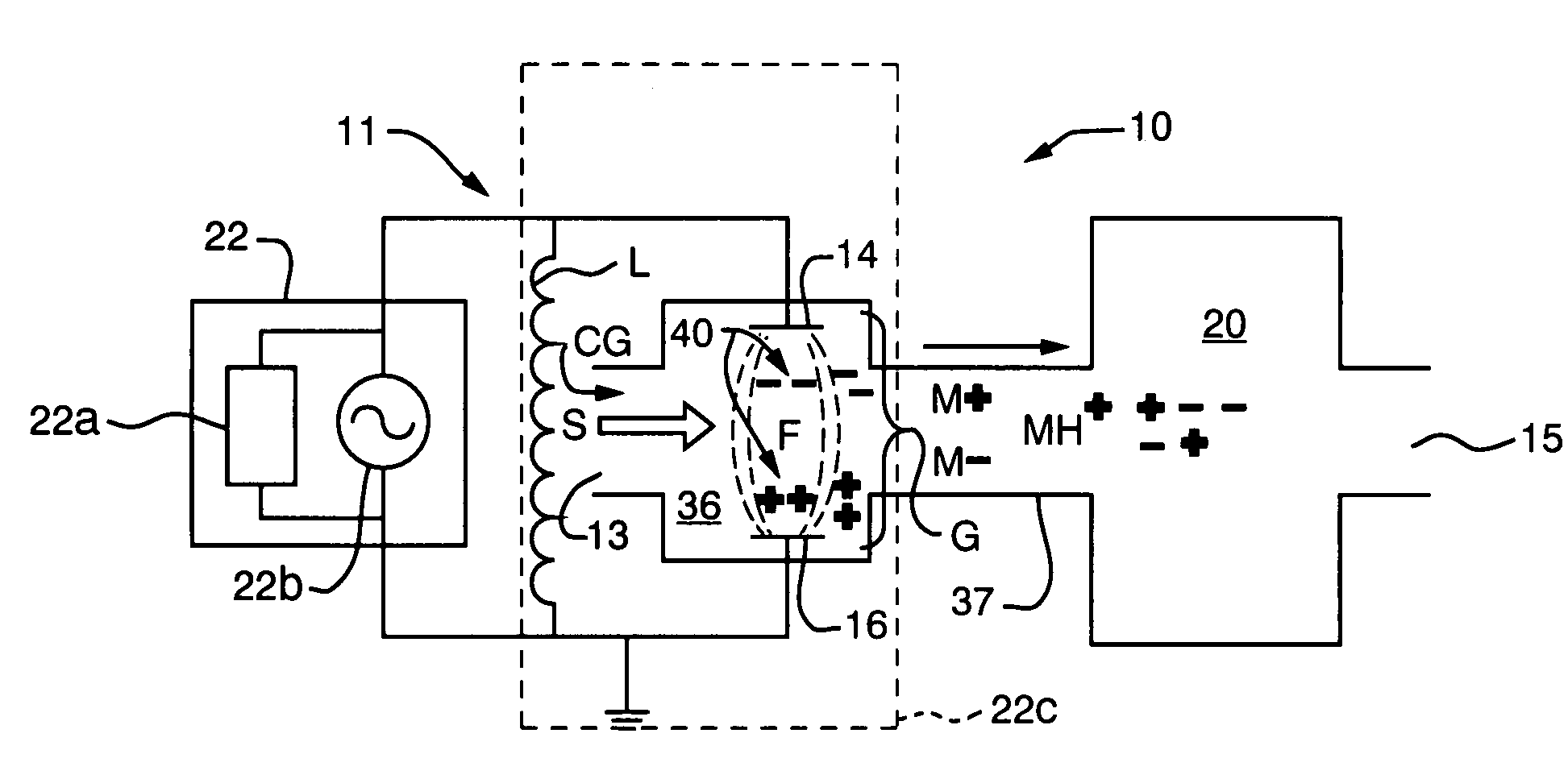
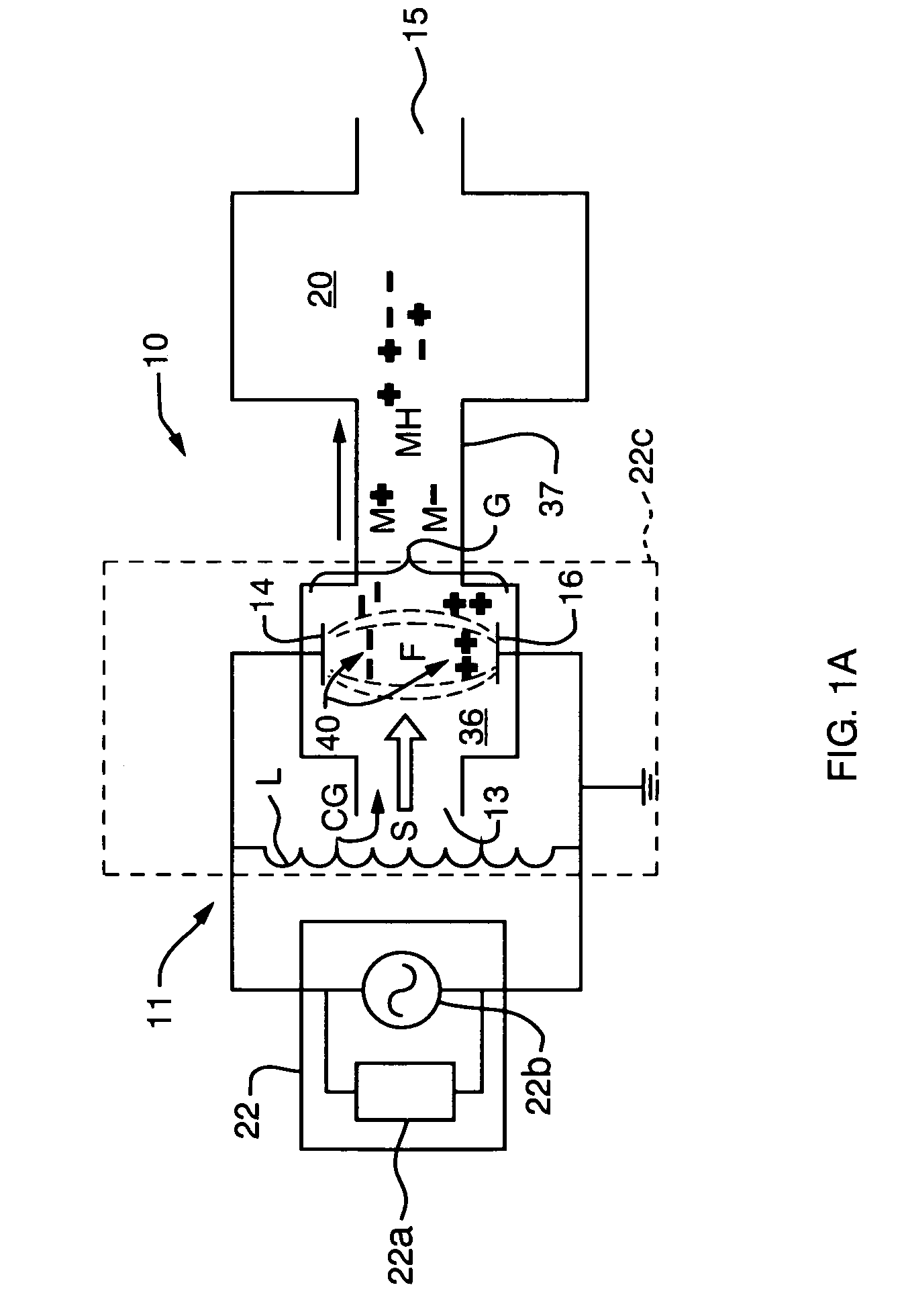
[0053]FIG. 1A is a generalized block diagram of a system 10 in practice of the invention used to analyze the composition of chemical compounds in a gas sample S. The system 10 includes a capacitive discharge plasma ionization source 11 and a detector 20. The detector may be a mass spectrometer (MS), ion mobility spectrometer (IMS), high-field asymmetric waveform ion mobility spectrometer (FAIMS), time-of flight spectrometer (TOF), or the like. In this embodiment, the capacitive discharge plasma ionization source 11 is separate from but in communication with spectrometer 20. Alternatively, the source 11 may be integrated into the spectrometer to form an integrated system 10.

[0054]Capacitive discharge plasma ionization source 11 includes a pair of electrodes 14, 16, which are preferably isolated, or insulated, as further described below. When a sufficient voltage is supplied across electrodes 14, 16, a discharge field F is established. Now the gas is flowed into the field in the gap G...


PUM

PropertyMeasurementUnit
Timeaaaaaaaaaa
Electric potential / voltageaaaaaaaaaa

Abstract

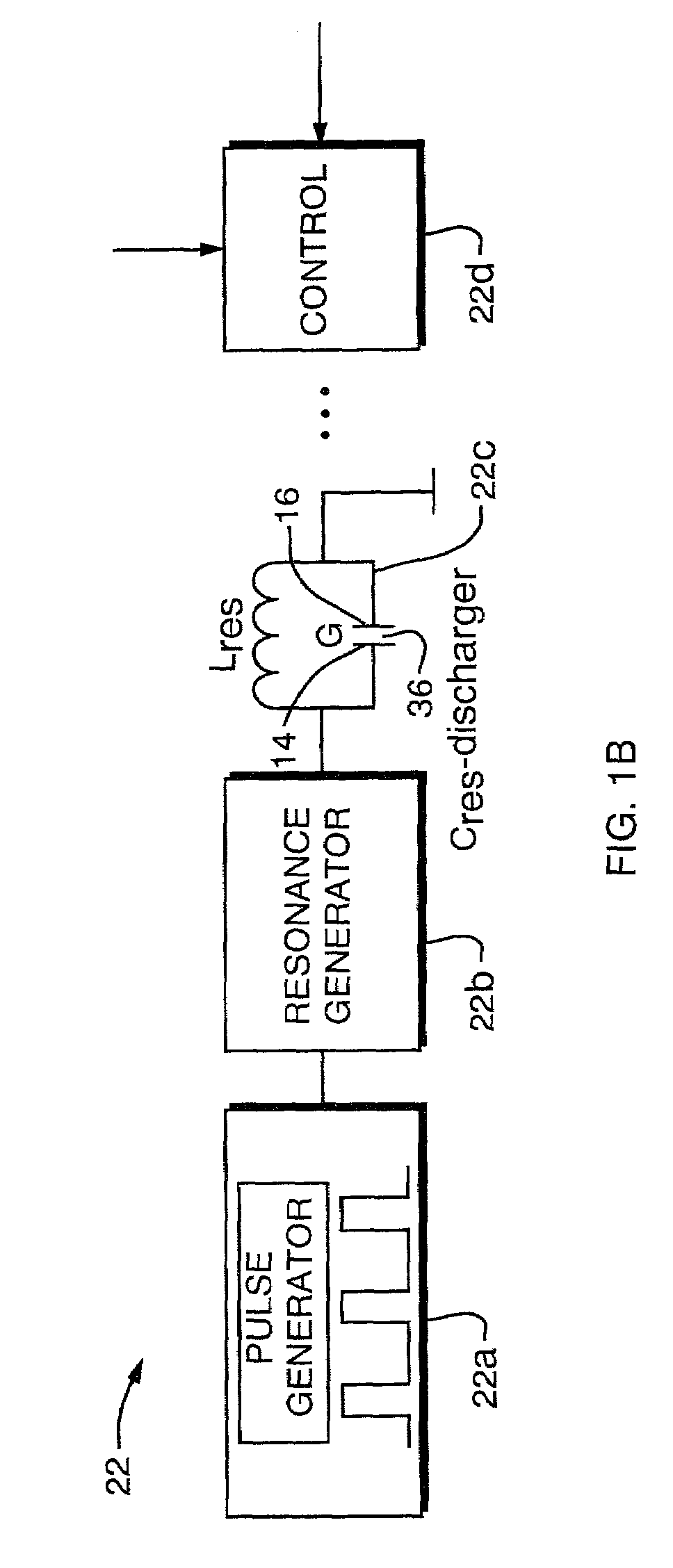
In a system for chemical analysis, an RF-driven plasma ionization device including a pair of spaced-apart and plasma-isolated electrodes, the electrodes are connected to a power source wherein the electrodes act as plates of a capacitor of a resonant circuit, the gas electrically discharges and creates a plasma of both positive and negative ions, and the voltage is applied as a continuous alternating waveform or as a series of pulses, such as a packet waveform.

Description

CROSS REFERENCE TO RELATED APPLICATIONS[0001]This application claims the benefit of a prior U.S. Provisional Application Ser. No. 60 / 310,902 filed Aug. 8, 2001 entitled, “Miniature Atmospheric Pressure Capacitive Discharge Ionization Source”, Ser. No. 60 / 335,219 filed Oct. 25, 2001 entitled “Radio Frequency Capacitive Discharge Ionizer for Analyzer”, Ser. No. 60 / 340,815 filed Dec. 12, 2001 entitled “Radio Frequency Capacitive Discharge Ionizer for Analyzer”, and Ser. No. 60 / 388,052 filed Jun. 12, 2002 entitled “Plasma Ionization Source for Metal Ion and Other Analysis”, the entire contents of all of such applications being hereby incorporated by reference.BACKGROUND OF THE INVENTION[0002]The present invention relates to an ionization source, and more particularly, to a gas-discharge ionizer.[0003]Creation of ionized particles is a useful tool for many applications, such as for ignition of lasing or to assist chemical analysis, among other uses. In some equipment, high energy radioac...

Claims


Application Information

Patent Timeline
IPC IPC(8): B01D59/44G01N21/68G01N27/62G01N27/68H01J49/10H01J49/26H01J49/40H01S3/223H05H1/24H05H1/46
CPCG01N21/68G01N27/622H01J37/32091H01J49/0095H01J49/105H05H1/24H05H1/46H01S3/2232H05H1/2406H05H1/2418H05H1/466G01N27/623
Inventor MILLER, RAANAN A.NAZAROV, ERKINJON G.KRYLOV, EVGENYEICEMAN, GARY A.KAUFMAN, LAWRENCE A.
Owner DH TECH DEVMENT PTE
Learn More