Exhaust gas purifying apparatus

a technology of exhaust gas purification apparatus and filter, which is applied in the direction of machines/engines, separation processes, transportation and packaging, etc., can solve the problems of increasing the gas-flow resistance of the filter, increasing the load on the engine, and difficulty in sufficiently burning out the trapped pm on the apparatus using only the thermal energy of the exhaust gas, etc., to achieve the effect of accelerating the trapping of pm at the honeycomb structure, reducing the cost of operation and maintenance, and increasing the electric charg

Inactive Publication Date: 2009-04-07
TOYOTA JIDOSHA KK
View PDF37 Cites 6 Cited by
  • Summary
  • Abstract
  • Description
  • Claims
  • Application Information

AI Technical Summary

Benefits of technology

[0042]According to the present invention, trapping of the PM at the honeycomb structure is accelerated. This appears to be because the material having high dielectric co

Problems solved by technology

However, in the case of using such a filter, the trapped PM gradually blocks the filter and, further, the filter increases the gas-flow resistance and becomes a larger load on the engine.
In the case that the filter traps the PM in the exhaust gas, it is difficult to sufficiently burn out the trapped PM on the filter using only the thermal energy of the exhaust gas.
Therefore, the apparatus does not sufficiently burn the trapped PM, and an special treatment is necessary to do it.
Therefore, this reference does not disclose the

Method used


Image

  • Exhaust gas purifying apparatus
  • Exhaust gas purifying apparatus
  • Exhaust gas purifying apparatus

Examples


examples 1 to 5

Example 1

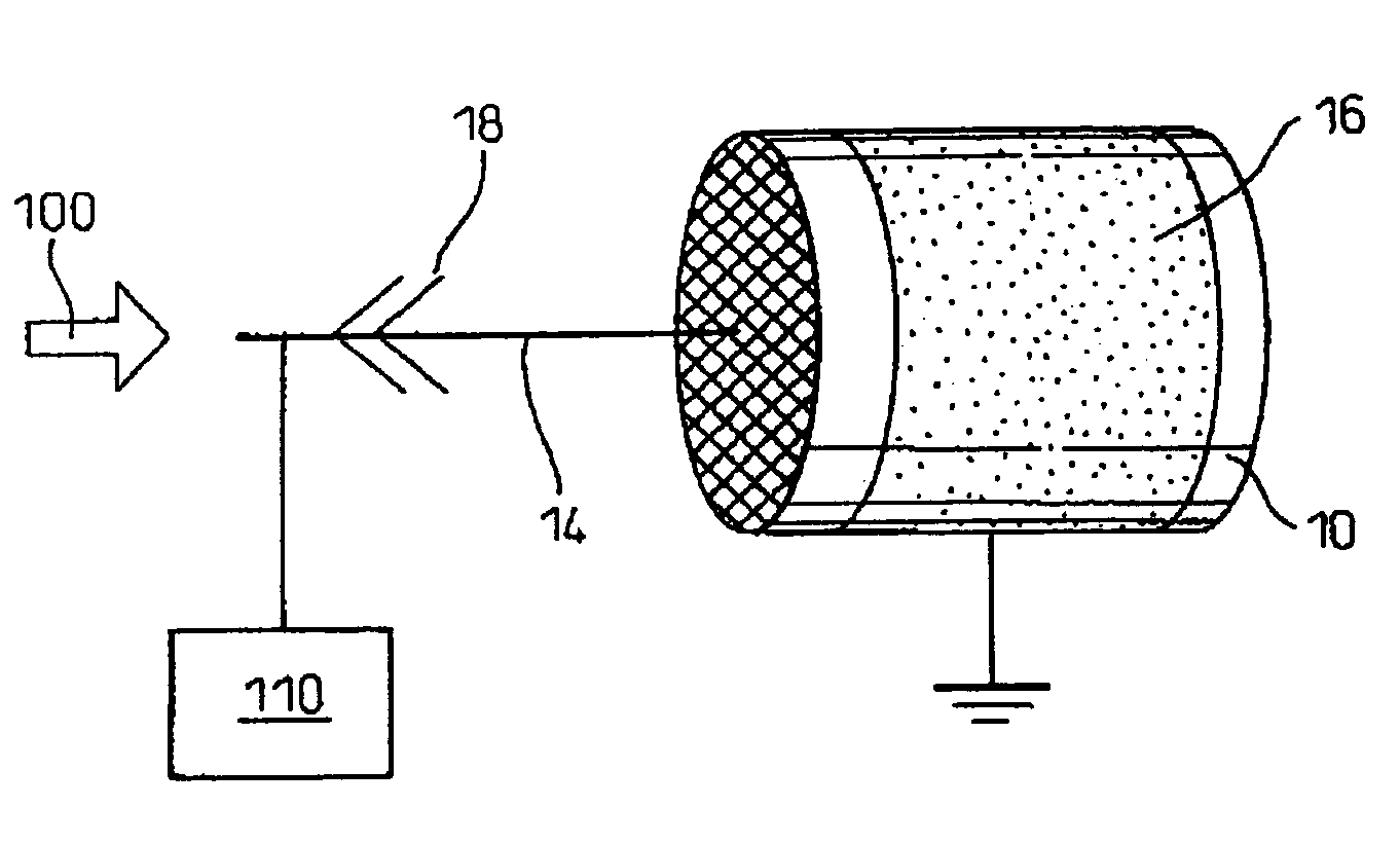
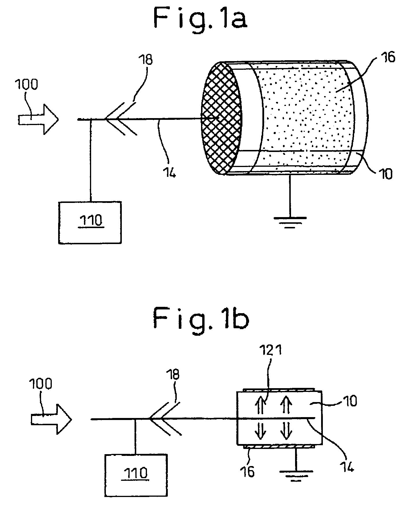
[0099]An exhaust gas purifying apparatus was provided according to the first embodiment of the present invention shown in FIGS. 1a and 1b. That is, around the circumference surface of a straight-flow type cordierite honeycomb structure (diameter: 30 mm and length: 50 mm, cell density: 200 cells / square inch, porosity: 65%, and average pore size: 25 μm (micro meters)), a stainless steel mesh (width: 40 mm, SUS 304, 300 mesh) was surrounded to be an outer electrode. On the center axis of the honeycomb structure, a center electrode (bar electrode) having needle electrodes was fixed. The exhaust gas purifying apparatus used for this example is shown in FIG. 4a.

example 2

[0100]The exhaust gas purifying apparatus of this example was the same as that of the example 1, except that a wall-flow type cordierite honeycomb structure (cell density: 300 cells / square inch, porosity: 65%, and average pore size: 25 μm) was used in place of the straight-flow type cordierite honeycomb of the example 1.

example 3

[0101]The exhaust gas purifying apparatus of this example was the same as that of the example 1, except that the honeycomb structure carries 4.0 g of a CeO2 powder and Pt (2 wt % on the basis of the amount of the CeO2 powder), the CeO2 powder being carried by wash coating and firing the honeycomb structure for 2 hours at the temperature of 450° C., and then the Pt being carried by impregnating a Pt dinitrodiammine complex aqueous solution into the honeycomb structure, drying and firing the obtained honeycomb structure for 2 hours at the temperature of 450° C.


PUM

PropertyMeasurementUnit
Temperatureaaaaaaaaaa
Angleaaaaaaaaaa
Diameteraaaaaaaaaa

Abstract

The present invention relates to an exhaust gas purifying apparatus, for trapping and burning PM, which comprises electrodes and an insulative honeycomb structure. The apparatus is characterized in that the electrodes make an electric field in the honeycomb structure, the electric field not being parallel with the cell passages of the honeycomb structure. Further the apparatus is characterized in that the electrodes make an electric field in the honeycomb structure, and that the honeycomb structure carries at least one metal selected from the group consisting of an alkali metal and an alkali earth metal; a material that generates oxygen radical by conducting an electric current therethrough; a manganese dioxide; and/or a material having a high dielectric constant.

Description

BACKGROUND OF THE INVENTION[0001]1. Field of the Invention[0002]The present invention relates to an apparatus for purifying exhaust gas from internal combustion engine and, in particular, to an apparatus for purifying the PM (particulate matter) emitted from a diesel engine.[0003]2. Description of Related Art[0004]A diesel engine is usually used for motor vehicles, particularly for large-size motor vehicles. Recently, it is required to reduce nitrogen oxide, carbon monoxide and hydrocarbon as well as the PM in the exhaust gas from the diesel engine. For this purpose, it is considered to improve an engine or optimize a combustion condition for controlling the generation of the PM, and to purify the generated PM in an exhaust gas.[0005]For removing the PM in an exhaust gas, a ceramic honeycomb filter having a number of cell passages (cell channels), a metal filter and a ceramic fiber filter that trap the PM are generally used. However, in the case of using such a filter, the trapped P...

Claims


Application Information

Patent Timeline
IPC IPC(8): B01J19/08B01D46/50B03C3/155F01N3/022F01N3/027
CPCB01D46/0063B01D46/2455B01D46/50F01N3/0222F01N3/027B01D46/2466B01D2046/2492B01D2279/30B03C3/155F01N2240/04F01N2250/02F01N2330/06F01N2330/30F01N2330/48B01D46/84B01D46/2482
Inventor HIRATA, HIROHITOKAKINOHANA, MASARUYAHAGI, HIDEO
Owner TOYOTA JIDOSHA KK
Why Eureka
Try Eureka