Ultra-low loadings of Au for stainless steel bipolar plates
a technology of stainless steel bipolar plates and low loading, applied in the field of fuel cells, can solve the problems of increasing the internal resistance reducing the performance of the fuel cell, and high cost of metals which meet the criteria
- Summary
- Abstract
- Description
- Claims
- Application Information
AI Technical Summary
Benefits of technology
Problems solved by technology
Method used
Image
Examples
first embodiment
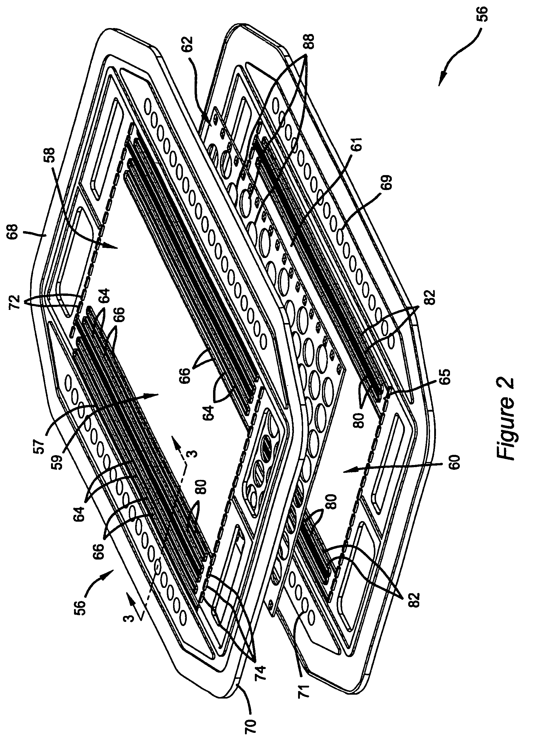
[0033]FIG. 2 is an exploded view of an exemplary bipolar plate 56 that may be used in accordance with the present invention. The bipolar plate 56 comprises a first exterior metal sheet 58, a second exterior metal sheet 60, and an interior spacer metal sheet 62 interjacent the first metal sheet 58 and the second metal sheet 60. The exterior metal sheets 58 and 60 are made as thin as possible and may be formed by stamping, or any other conventional process for shaping sheet metal. The external sheet 58 has a first working face 59 on the outside thereof which confronts a membrane electrode assembly (not shown) and is formed so as to provide a flow field 57. The flow field 57 is defined by a plurality of lands 64 which define therebetween a plurality of grooves 66 which constitutes the “flow field” through which the fuel cell's reactant gases (i.e. H2 or O2) flow in a meandering path form one side 68 of the bipolar plate to the other side 70 thereof. When the fuel cell is fully assemble...
second embodiment
[0039]In a second embodiment, a cross-sectional view of another electrically conductive fluid distribution element 100 is shown in FIG. 5. The element 100 is constructed with a thin, substrate sheet 102 having foam flow fields 106. This bipolar plate features a thin barrier sheet 102, preferably made from a solid titanium metal sheet, with foam 106 (about one-half to about 3 millimeters thick) attached as by welding or brazing to both sides thereof. The sheet 102 forms the gas barrier and the foam 106 forms the fluid flow fields. As can be seen, foam 106 has opposed major surfaces 110 and 111. The foam 106 has one major surface 110 facing the metal sheet 102 and another major surface 111 opposite 110. Typically, major surface 111 faces the MEA. As shown in FIGS. 5 and 6, major surface 111 forms the outer surface of electrically conductive element 100. Foams can be prepared as metal foams or carbon-based foams. Metals that can be prepared as a solid foam include copper, aluminum, nic...
third embodiment
[0042]In a third embodiment, as can be seen in FIG. 7, the electrically conductive coating 94 can be deposited onto another electrically conductive fluid distribution element 112 that includes a polymeric material 113 with a conductive fibrous filler 114 having a through-plane orientation which provides a path of conductivity through the element may be used. This is a composite material. The polymeric material 113 is preferably a suitable thermoset polymer and more preferably selected from the group of material including silicone, poly-isobutylene, epoxy, vinyl ester and phenolic. Alternately, the polymeric material 113 is preferably a suitable thermoplastic and more preferably selected from the group of materials including polypropylene, ethylene tetrafluoro-ethylene (ETFE), nylon and rubber-modified polypropylene. While the foregoing thermoset and thermoplastic polymers containing a conductive fibrous filler are presently preferred, one skilled in the art will readily recognize th...
PUM
| Property | Measurement | Unit |
|---|---|---|
| aspect ratio | aaaaa | aaaaa |
| pressure | aaaaa | aaaaa |
| cathodic current | aaaaa | aaaaa |
Abstract
Description
Claims
Application Information
 - R&D
- Intellectual Property
- Life Sciences
- Materials
- Tech Scout
- Unparalleled Data Quality
- Higher Quality Content
- 60% Fewer Hallucinations
Browse by: Latest US Patents, China's latest patents, Technical Efficacy Thesaurus, Application Domain, Technology Topic, Popular Technical Reports.
© 2025 PatSnap. All rights reserved.Legal|Privacy policy|Modern Slavery Act Transparency Statement|Sitemap|About US| Contact US: help@patsnap.com


