Eureka AIR delivers breakthrough ideas for toughest innovation challenges, trusted by R&D personnel around the world.

Filter for purifying hydrogen and method for manufacture thereof

a technology of purifying membrane and filter, which is applied in the direction of inorganic chemistry, chemical/physical processes, cable/conductor manufacturing, etc., can solve the problems of low yield, less than satisfactory durability of pd alloy film, and much worse performance, so as to facilitate the fabrication of the hydrogen permeation effect and improve the hydrogen permeation efficiency

Inactive Publication Date: 2010-02-16
DAI NIPPON PRINTING CO LTD
View PDF10 Cites 15 Cited by
  • Summary
  • Abstract
  • Description
  • Claims
  • Application Information

AI Technical Summary

Benefits of technology

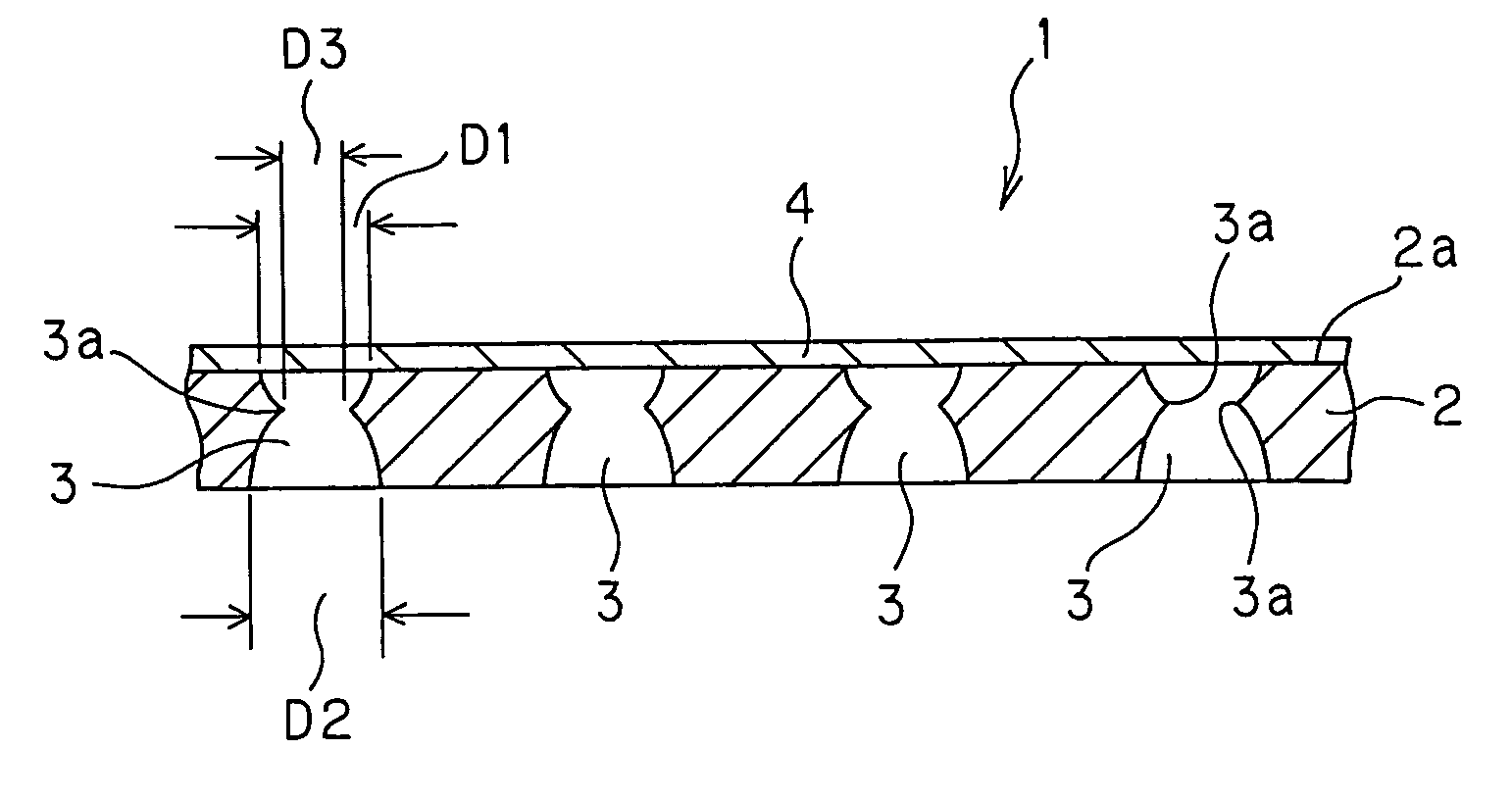
The invention provides a hydrogen-purification membrane with improved hydrogen permeation efficiency and a process for its fabrication. The membrane has a porous support substrate with a plurality of pores joined to a Pd alloy film. The pores have a narrowest portion and the opening diameter of the pores on the side joined to the Pd alloy film must meet certain conditions. The membrane has a high total opening area and the pores have a high aspect ratio. The membrane has a high hydrogen purification efficiency and the process for its fabrication involves forming resist patterns, etching the support substrate, applying an insulating film, and plating a Pd alloy film.

Problems solved by technology

Problems with the solid polymer type fuel cell (PEFC) are, however, that its electrode catalyst is poisoned by a slight amount of CO and its performance becomes much worse especially in high current density regions, because platinum is used as the catalyst and because of low operation temperature.
However, the Pd alloy film and the support must be separately attached to the reformer, giving rise to a problem in connection to the workability for obtaining good sealing, and a problem that friction occurs between the Pd alloy film and the support, rendering the durability of the Pd alloy film less than satisfactory.
With the hydrogen-purification membrane set forth in JP(A)2004-57866, however, yields are low with difficulty in cutting down on fabrication costs, because upon the resist formation and the etching at the step of providing through-holes by etching of the flat metal sheet with the Pd alloy film formed on one surface from its back surface side, the Pd alloy film is susceptible to break down.
Further, etching from one side of the flat metal sheet causes the opening diameter of each through-hole to become inevitably larger than the thickness of the flat metal sheet and the through-hole pitch to become wide, imposing limitations on the number of through-holes formed per unit area.
A problem with the hydrogen-purification membrane set forth in JP(A)2002-292259, on the other hand, is that much time is taken to form the metal base film on the Pd alloy film by electrolytic plating, and it is difficult to form a metal base film having sufficient strength and large thickness.
There is another problem that the resist is likely to remain on micro-openings in the formed metal base film.
Such voids would otherwise be responsible for pinhole defects of the Pd alloy film.
This causes a complex process control and offers obstacles to cutting down on fabrication costs.

Method used


Image

  • Filter for purifying hydrogen and method for manufacture thereof
  • Filter for purifying hydrogen and method for manufacture thereof
  • Filter for purifying hydrogen and method for manufacture thereof

Examples


example 1

[0102]A SUS304 material with a thickness (T) of 50 μm was used as the electrically conductive support substrate, and a photosensitive resist material (OFPR made by Tokyo Ohka Kogyo Co., Ltd.) was coated on both surfaces of the SUS304 material by means of dipping (at a coating amount of 7 μm as measured on a dry basis). Then, a photomask A having a plurality of circular openings, each having an opening size (diameter) of 30 μm, at a pitch of 120 μm was placed on one of the above resist coating films while, at the same time, a photomask B having a plurality of circular openings, each having an opening size (diameter) of 55 μm, at a pitch of 120 μm was placed on the other resist coating film. Via those photomasks A and B, the resist coating films were exposed to light, and then developed using sodium hydrogencarbonate. Here, the center of each opening in the photomask A was in alignment with the center of each opening in the photomask B with the SUS304 material placed between them.

[010...

example 2

[0126]A SUS304 material with a thickness (T) of 50 μm was used as the electrically conductive support substrate, and a photosensitive resist material (OFPR made by Tokyo Ohka Kogyo Co., Ltd.) was coated on both surfaces of the SUS304 material by means of dipping (at a coating amount of 7 μm as measured on a dry basis). Then, a photomask C having a plurality of circular openings, each having an opening size (diameter) of 65 μm, at a pitch of 150 μm was placed on one of the above resist coating films while, at the same time, a photomask D having a plurality of circular smaller openings, each having an opening size (diameter) of 30 μm, at a pitch of 150 μm was placed on the other resist coating film. Via those photomasks C and D, the resist coating films were exposed to light, and then developed using sodium hydrogencarbonate. Here, the center of each opening in the photomask C was in alignment with the center of each opening in the photomask D with the SUS304 material placed between t...


PUM

PropertyMeasurementUnit
pressureaaaaaaaaaa
thicknessaaaaaaaaaa
thicknessaaaaaaaaaa

Abstract

A hydrogen-purification membrane comprises a Pd alloy film joined to one surface of a porous support substrate. Each pore in the porous support substrate is such that between the thickness T of the porous support substrate, the opening diameter D1 of the pore on the side joined to the Pd alloy film and the opening diameter D2 of the pore on the opposite side, there are relations represented by 1.0≦D1 / T≦5.0 and 1.0≦D2 / T≦5.0, and between the opening diameter D1 of the pore on the side joined to the Pd alloy film, the opening diameter D2 of the pore on the opposite side and the opening diameter D3 of the narrowest portion of the pore there are relations represented by D3 / D1<0.8, D3 / D2<0.9 and D3<250 μm. Furthermore, the total opening area of the pores on the side joined to the Pd alloy film accounts for 20 to 80% of the area of the porous support substrate.

Description

TECHNICAL FIELD[0001]The present invention relates generally to a hydrogen-purification membrane and its fabrication process, and more particularly to a hydrogen-purification membrane used with a reformer or other device for reforming a variety of hydrocarbon fuels by steam reforming to generate hydrogen-rich gas, and a process capable of facilitating its fabrication.BACKGROUND ART[0002]Recently with global environments as well as energies and resources, problems have come to the surface, and fuel cells now attract attention as one of energy supply systems for putting them in harmony with the industry. A fuel cell is a power generator wherein hydrogen-rich gas obtained by reformation of previously supplied hydrogen gas, or hydrocarbonaceous fuels such as natural gas, gasoline, butane gas and methanol is allowed to react electrochemically with atmospheric oxygen for giving direct access to electricity. A typical fuel cell using the hydrogen-rich gas comprises a reformer for steam ref...

Claims


Application Information

Patent Timeline
Patent Type & Authority Patents(United States)
IPC IPC(8): B01D53/22B01D71/02
CPCB01D53/228B01D67/0062B01D69/02B01D71/022C01B3/505C23F1/02C23F1/28C25D7/00B01D2325/021Y10T428/12951C01B2203/047Y10S55/05Y10T428/249953C01B2203/041B01D2325/0214B01D71/02231B01D69/105B01D69/1213B01D67/0069B01D67/0083B01D2256/16B01D2325/04B01D2325/0283
Inventor MAEDA, TAKANORIYAGI, HIROSHIHARAYAMA, ASAKO
Owner DAI NIPPON PRINTING CO LTD
Why Eureka
Eureka Blog
Learn More