Electrolytic capacitors with alternate cathode materials for use in pulse discharge applications

a capacitor and cathode technology, applied in the field of cathode electrodes within electrolytic capacitors, can solve the problems of consuming electrolyte, reducing capacitor performance, and reducing capacitor performance, so as to avoid capacitor swelling, reduce manufacturing costs, and simple water and alcohol rinse

Active Publication Date: 2010-05-11
PACESETTER INC
View PDF46 Cites 30 Cited by
  • Summary
  • Abstract
  • Description
  • Claims
  • Application Information

AI Technical Summary

Benefits of technology

[0012]The present invention is directed to the use of a non-surface-area-enhanced metal or metal alloy electrode as a cathode electrode within an electrolytic capacitor and to an electrolytic capacitor including the cathode electrode of the present invention. According to the present invention, it has been found possible to use a titanium or similar metal or metal alloy foil as the cathode in a multiple anode flat, stacked capacitor configuration. An electrolytic capacitor including the cathode electrode of the present invention may be used in pulse discharge applications, such as ICDs, without discharge energy loss.
[0015]The multiple anode flat, stacked capacitor configuration of the present invention is preferably impregnated with an ethylene glycol based electrolyte, such as an ammonium azelate and boric acid in ethylene glycol or an ammonium borate and ammonium phosphate in ethylene glycol. A cathode depolarizer, preferably a nitroaromatic compound such as nitrobenzene, nitroacetophenone, or nitroanisole, more preferably o-nitroanisole or 3′ nitroacetophenone, may be added to the electrolyte to improve the gas evolution behavior of the cathode of the present invention.
[0017]According to the present invention, despite a 120 Hz bridge capacitance measurement lower than with etched aluminum, the use of titanium and similar cathode materials will inhibit gas production and avoid capacitor swelling. Furthermore, the ratio of stored energy to delivered energy is acceptable for a capacitor with 30 micron or thinner titanium. The invention is especially useful when the capacitor is applied to a pulse discharge application since the 120 Hz capacitance is substantially affected. Preparation of an unetched and uncoated cathode according to the present invention also reduces manufacturing expense, as a simple water and alcohol rinse is all that is necessary to prepare the cathode foil for use.

Problems solved by technology

However, due to the higher capacitance values achieved with multiple anodes, traditional chemically etched aluminum cathodes provide insufficient capacitance coverage at the desired thickness of 30 microns or less.
If the cathode develops a positive potential, several undesirable effects can occur including oxide buildup on the cathode which reduces the capacitor performance, electrolysis that consumes electrolyte and deteriorates the performance of the capacitor with usage, and production of gaseous electrolysis byproducts that can cause swelling of the capacitor.
A conventional 30 micron aluminum cathode does not provide an adequate anode / cathode capacitance ratio for full 120 Hz capacitance realization in a multiple anode flat, stacked capacitor configuration.
Known high capacitance cathode technologies present significant problems.
Etched aluminum cathodes are technologically limited and can not support the high capacitance required when more than two anodes are placed adjacent to each other in a capacitor stack.
Coated cathodes are difficult to obtain commercially and reliably.
The titanium nitride coating process is expensive.
Metal oxides are difficult to coat in high purity without chloride contamination.
Conductive polymers have exhibited stability issues under certain loads and uses.

Method used


Image

  • Electrolytic capacitors with alternate cathode materials for use in pulse discharge applications
  • Electrolytic capacitors with alternate cathode materials for use in pulse discharge applications
  • Electrolytic capacitors with alternate cathode materials for use in pulse discharge applications

Examples


example 1

[0067]Finished capacitors according to the present invention were constructed with several different raw metals as cathode material. Grade 1 titanium, grade 2 titanium and nickel foils were all used as cathode material. Each metal sample was pretreated with an alcohol and water rinse before being used in a capacitor. As a control, capacitors were also constructed with Becromal Kappa 30B cathode material.

[0068]Each capacitor was impregnated with an ammonium azelate and boric acid in ethylene glycol electrolyte and then tested. The total delivered energy, stored energy, and ESR were measured for each capacitor tested. Four capacitors were constructed and measured for each type of cathode material. Table 1, below, displays the average of these four measurements for each type of capacitor.

[0069]

TABLE 1Total DeliveredType of CathodeEnergy (J)ESR (Ω)Stored Energy (J)Kappa 30B (control)15.651.0617.87Grade 1 Titanium15.501.0617.60Grade 2 Titanium15.530.9917.68Nickel15.620.9917.87

[0070]These...

example 2

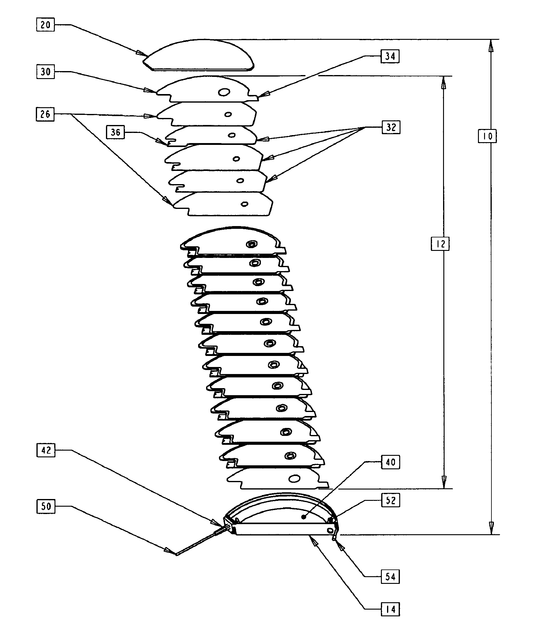
[0073]Slide capacitors were constructed with a four anode per layer stack, six layers of 0.25 mil Kraft paper in 1.0 g / cc density (available from MEDielectrics, Inc. of Mt. Holly Springs, Pa.), two grade 2 titanium cathode foils (nominal thickness 0.001″), an electrolyte and a platinum wire separated from a cathode by one sheet of paper. The slide capacitors were built as follows: glass slide—titanium cathode—three layers of Kraft paper—welded four anode stack—two layers of Kraft paper—platinum wire—one layer Kraft paper—titanium cathode—glass slide. The platinum wire served to measure the pulse discharge voltage at the cathode.

[0074]The slide capacitors were vacuum impregnated with one of the following electrolytes: (a) ammonium azelate and boric acid in ethylene glycol (hereinafter “Electrolyte A”), (b) ammonium azelate and boric acid in ethylene glycol with 1% o-nitroanisole (hereinafter “Electrolyte B”), (c) ammonium azelate and boric acid in ethylene glycol with 1% 3′-nitroacet...

example 3

[0081]To determine if placement of the platinum wire in the slide capacitors of Example 2 impacted the discharge voltage measured by the oscilloscope, several slide capacitors with two platinum wires were constructed. These slide capacitors contained two platinum wires side by side, between the same two layers of paper, at different positions. Each platinum wire was hooked to a separate oscilloscope probe tip. Two oscilloscope channels were used to measure the pulse discharge voltage at each platinum wire simultaneously.

[0082]This test revealed differences in the measured voltage at the two leads. In a slide capacitor impregnated with Electrolyte C the reported pulse discharge voltages of the two leads varied by about 2.5V after the first pulse. After repeated pulsing, the disparity between the two voltage measurements increased. After 20 pulses, the reported discharge voltage of one lead was approximately five volts higher than that of the other lead. In a slide capacitor impregnat...


PUM

PropertyMeasurementUnit
thickaaaaaaaaaa
thickaaaaaaaaaa
thickaaaaaaaaaa

Abstract

A metal or metal alloy foil substrate, preferably an unetched and uncoated metal or metal alloy foil substrate, such as but not limited to titanium, palladium, lead, nickel, tin, platinum, silver, gold, zirconium, molybdenum, tantalum, palladium-silver alloy, platinum-rhodium alloy, platinum-ruthenium alloy, and / or platinum-iridium alloy, is used as the cathode in an electrolytic capacitor, preferably an aluminum electrolytic capacitor having a multiple anode flat, stacked capacitor configuration. Despite a 120 Hz bridge capacitance measurement lower than with etched aluminum, the use of an unetched and uncoated metal or metal alloy foil cathode according to the present invention will inhibit gas production and not cause the capacitor to swell. Furthermore, an electrolytic capacitor built with a 30 micron unetched and uncoated foil cathode according to the present invention can deliver a stored to discharge energy ratio sufficient for use in pulse discharge applications, such as an in an ICD.

Description

BACKGROUND OF THE INVENTION[0001]1. Field of the Invention[0002]The present invention relates to cathode electrodes within electrolytic capacitors and, more particularly, to the use of a titanium or similar metal or metal alloy electrode as a cathode electrode within an electrolytic capacitor for use in pulse discharge applications and to an electrolytic capacitor including the cathode electrode of the present invention.[0003]2. Related Art[0004]Compact, high voltage capacitors are utilized as energy storage reservoirs in many applications, including implantable medical devices. These capacitors are required to have a high energy density since it is desirable to minimize the overall size of the implanted device. This is particularly true of an Implantable Cardioverter Defibrillator (ICD), also referred to as an implantable defibrillator, since the high voltage capacitors used to deliver the defibrillation pulse can occupy as much as one third of the ICD volume.[0005]Implantable Card...

Claims


Application Information

Patent Timeline
Patent Type & Authority Patents(United States)
IPC IPC(8): H01G9/04
CPCA61N1/375H01G9/06H01G9/048H01G9/035
Inventor BEAUVAIS, W. JOSEPHMOORE, MELISSA A.STEVENS, JAMES L.STRANGE, THOMAS F.FEGER, CHRISTOPHER R.
Owner PACESETTER INC
Why Eureka
Try Eureka