
Radiation source and device

a technology of radiation source and device, applied in the direction of optical radiation measurement, discharge tube luminescnet screen, instruments, etc., can solve the problems of reducing flux density, particularly severe problems, and difficult to produce individual halogen lamps of correspondingly large widths, and achieve reliable heat dissipation, high thermal conductivity, and high efficiency

Inactive Publication Date: 2010-10-26
ADPHOS INNOVATIVE TECH +1
View PDF24 Cites 11 Cited by
  • Summary
  • Abstract
  • Description
  • Claims
  • Application Information

AI Technical Summary

Benefits of technology

[0011]In an embodiment that is preferred because of its simplicity, at least one end of the halogen lamp is bent with a radius of curvature such that the end section is substantially at a right angle to the longitudinal direction of the lamp. Hence the lamp connectors are directed substantially at right angles to the longitudinal extent of the tube and the filament, so that it is a simple matter to position the connectors in a row behind the linear array of halogen lamps.
[0012]In an alternative embodiment at least one end of the halogen lamp comprises a section bent into a C shape, so that the outermost point of the base associated with this end is displaced inward by a slight amount with respect to the outermost point of the glass tube at this end. It is also possible to construct halogen lamps with a glass tube having this latter geometry at one end while the other end has the rectangularly bent configuration described above. The last-mentioned design enables (although with somewhat greater constructional effort regarding the halogen lamp) an improved means of arranging the radiation sources “seamlessly” end to end in a row, in order to achieve an extremely wide irradiation field with almost completely constant radiation flux density, because this design makes more space available for the structures supplying power to the lamp bases.
[0016]In particular there is provided in the reflector at least one compressed-air flow channel with outlet openings (“nozzles”) directed towards the ends of the halogen lamp, through which cold compressed air—or another coolant gas—is conducted into these regions. In a preferred embodiment of this idea a plurality of compressed-air flow channels is provided in the reflector, each of which comprises outlet openings so disposed and constructed that the compressed air passing through them becomes turbulent around the ends or regions near the ends of the glass tube. This turbulent flow ensures reliable dissipation of the heat from all of the surface regions that are to be cooled.
[0018]An especially advantageous way to dissipate heat is provided by 25 reflectors constructed as massive extruded profiles of a material with high thermal conductivity, in particular aluminum or an aluminum alloy. The reason is that in such reflectors the flow channels for the coolant fluid (whether embodied as channels for compressed air or for water) can be incorporated particularly easily, and the massive construction of the reflector endows it with a high heat capacity and thus contributes toward making the radiation of heat away from the radiation source more uniform, even if there are slight inhomogeneities in the primary radiation profile of the spiral filament or slight fluctuations in the supplied voltage.
[0019]A reflector profile of this kind that provides especially advantageous reflection properties, which contribute to a long working life of the halogen lamp, and is also especially easy to manipulate in an irradiation system with modular construction, has a cross-sectional shape with a substantially rectangular external contour and a substantially W-shaped reflector surface, such that in particular two or three coolant flow channels are incorporated into the foot region between the “W” and the rectangular external contour.
[0021]Such an irradiation arrangement can be used in particular for the NIR drying of lacquers or plastic coatings—specifically powder lacquers—as well as for manufacturing plastic laminates or the thermal treatment (specifically drying and / or producing cross-linkage) of thin-layer structures, especially thermally sensitive substrates in the area of semiconductor and display technology, and also in other applications such that the implementation of wide irradiation zones with almost ideally constant radiation flux density enhances the productivity of the procedure.

Problems solved by technology

This is problematic in the case of applications that require a constant radiation flux density over the whole width of the product, because these regions are in principle not functional, so that the usable width of the irradiation zone, as far as processing technology is concerned, is smaller than the length of the radiation source.
However, to produce individual halogen lamps of a correspondingly large width is technically difficult and extremely expensive.
However, the above-mentioned fact that the radiation flux density decreases near the bases of the glass tube of an individual halogen lamp proves to be a particularly severe problem in this regard.
Hence the currently available radiation-source constructions cannot be employed for such applications if it is essential that the radiation flux density be constant over the entire width of the processing region.

Method used


Image

  • Radiation source and device
  • Radiation source and device
  • Radiation source and device

Examples


Embodiment Construction

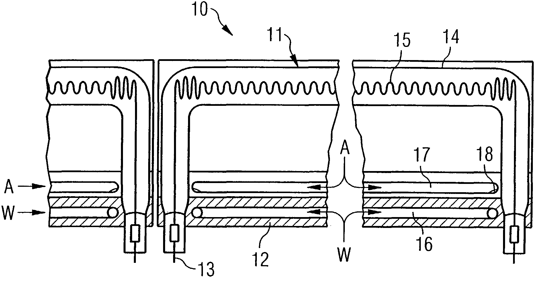
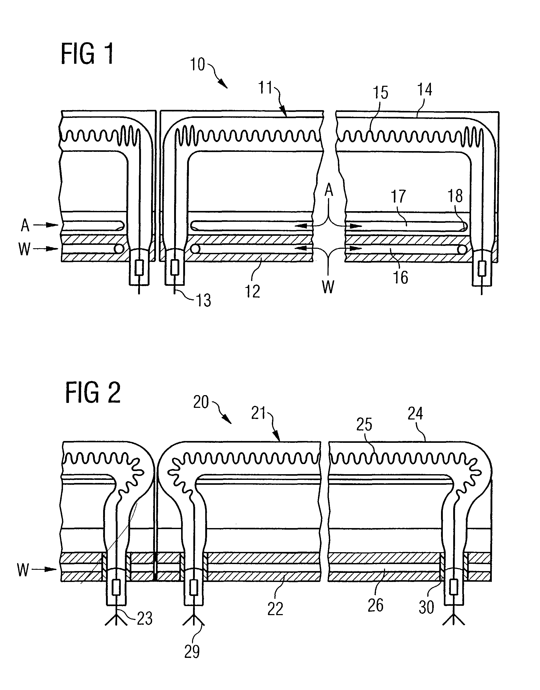
[0026]FIG. 1 shows part of an NIR irradiation arrangement 10 for technological purposes, with a plurality of halogen filament lamps 11 disposed in a row extending in their long directions and aligned with one another, with each of which there is associated an elongated reflector 12 made of an aluminum extruded profile.

[0027]The basic structure of the reflector is known per se from the applicant's patent document EP 0 999 724 A2 and hence is not explained further here. In the following reference will be made only to special cooling devices disposed in the interior or the vicinity of the reflector.

[0028]As can be seen in the figure, the halogen filament lamp 11 has a glass body in the shape of a tube 14, which contains in its center an elongated spiral filament 15 and has at each of its two ends a connector pin 13. The lamp is operated at high voltage and therefore at an elevated operating temperature, above 2500 K and in particular above 2900 K, so that the radiation it emits has its...


PUM

PropertyMeasurementUnit
wavelengthaaaaaaaaaa
temperatureaaaaaaaaaa

Abstract

Radiation source for electromagnetic radiation the major effective component of which is in the near-infrared region, in particular in the wavelength region between 0.8 μm and 1.5 μm, to form an elongated irradiation zone, with an elongated halogen lamp comprising a glass body that has a tubular shape with bases at the ends and contains at least one spiral filament, and with an elongated reflector, such that the bases of the halogen lamp are disposed in the region of the reflector surface or behind it with reference to the position of the halogen lamp, wherein the ends of the halogen lamp are bent around toward the reflector and the spiral filaments or at least one of them is made thicker or is more densely wound in the bent region of the glass body, in such a way that the radiation flux density of the radiation source is substantially constant in the long direction of the source, between the outermost points of the bases.

Description

CROSS REFERENCE TO RELATED APPLICATIONS[0001]This application claims the benefit of German Patent Application Number 100 46 161.1, filed Sep. 18, 2000, German Patent Application Number 100 51 905.9 filed Oct. 19, 2000, and PCT International Patent Application Number PCT / EP01 / 10539 filed Sep. 12, 2001, which are hereby incorporated by reference in their entirety.BACKGROUND OF THE INVENTION[0002]The invention relates to a radiation source according to the pre-characterizing clause of Claim 1 and to an arrangement for irradiation that incorporates such a radiation source.[0003]Previous patent applications submitted by the present applicant, for example DE 197 36 462 A1, WO 99 / 42774 and P 10024731.8 (unpublished), have disclosed methods for treating surfaces, processing materials and manufacturing composite materials that involved the employment of electromagnetic radiation with a major effective component in the near-infrared region, in particular in the wavelength region between 0.8 μ...

Claims


Application Information

Patent Timeline
Patent Type & Authority Patents(United States)
IPC IPC(8): G01J1/00B29C35/08H01K1/28H01K7/00
CPCB29C35/08B29C2035/0822B32B2310/0825H01K1/28H01K7/00
Inventor BÄR, K.O. KAIGAUS, RAINERGESELL, GÜNTHERBERGE, TORSTEN
Owner ADPHOS INNOVATIVE TECH
Learn More