Solar hydrogen charger

a solar energy and charger technology, applied in the field of solar energy chargers, can solve the problems of low efficiency, limited system life, and high overpotential of photoelectrodes, and achieve the effects of reducing irradiance losses, avoiding corrosion of important semiconductor photoelectrodes, and allowing maximum direct solar irradian

Active Publication Date: 2010-11-16
GAS TECH INST
View PDF11 Cites 5 Cited by
  • Summary
  • Abstract
  • Description
  • Claims
  • Application Information

AI Technical Summary

Benefits of technology

[0015]To address the issues set forth herein above, the invention disclosed and claimed herein is an apparatus for hydrogen generation and storage comprising a photoelectrochemical direct hydrogen generator having a water inlet connectable with a water supply and having a hydrogen gas outlet, an electrochemical compressor having a hydrogen gas inlet in fluid communication with the hydrogen gas outlet and having a compressed hydrogen gas outlet, and a hydrogen gas storage tank having a compressed hydrogen gas inlet in fluid communication with the compressed hydrogen gas outlet. In accordance with one particularly preferred embodiment, the photoelectrochemical direct hydrogen generator comprises at least one photoelectrochemical cell comprising a water permeable photoelectrode. The water permeable photoelectrode comprises a light sensitive, nano-crystalline catalytic material layer, a polymer electrolyte membrane layer, a metallic substrate layer disposed between the light sensitive, nano-crystalline catalytic material and the polymer electrolyte directly adjacent to the polymer electrolyte membrane layer, and at least one photovoltaic device connected in series to the light sensitive, nano-crystalline catalytic material layer and disposed between the light sensitive, nano-crystalline catalytic material layer and the metallic substrate layer. Each of the light sensitive, nano-crystalline catalytic material layer, the polymer electrolyte membrane layer, the metallic substrate layer and the at least one photovoltaic device is water permeable. Water from an electrolyte employed in the water-splitting apparatus of this invention permeates through the photoelectrode from the polymer electrolyte membrane layer to the light sensitive, nano-crystalline catalytic material layer at the surface, forming a three-phase zone, i.e., semi-conductor with electrochemical catalyst, water and product gases (hydrogen and oxygen). This helps to avoid corrosion of the important semiconductor photoelectrodes while also permitting maximum direct solar irradiance. The hydrogen thus generated is then removed from the housing for use or further processing as necessary. A suitable water permeable photoelectrode is disclosed in U.S. Pat. No. 7,241,950 B2, which patent is incorporated by reference herein in its entirety.
[0016]At least one, and preferably two or more, such photoelectrodes are disposed in the housing having at least one light transmissive wall. The photoelectrodes are arranged such that the light sensitive, nano-crystalline catalytic material layer is oriented in the direction of, and disposed at a distance from, the at least one light transmissive wall. The water-based electrolyte is disposed on the side of the photoelectrode on which is disposed the polymer electrolyte membrane layer and is precluded from coming between the light sensitive, nano-crystalline catalytic material layer and the at least one light transmissive wall. In this manner, sunlight striking the at least one light transmissive wall passes through the wall and directly strikes the light sensitive, nano-crystalline catalytic material layer of the photoelectrode without passing through an electrolyte layer. This reduces irradiance losses due to absorption or reflective scatter of sunlight striking or passing through an electrolyte layer as occurs in conventional systems.

Problems solved by technology

These low efficiencies are due in part to efficiency losses from sunlight absorption by a liquid electrolyte layer, impediments to the departure of product gases from the photoelectrodes due to electrolyte surface tension, and high overpotential of the photoelectrodes.
In addition, system life is limited by photocorrosion and electrochemical corrosion of the electrode.
Finally, in addition to all of the mechanical and operational issues, the costs of these devices are too high for wide use.
The current design of photoelectrodes is an additional hindrance to the development of improved photoelectrochemical systems because the semiconductors employed therein are fabricated on conductive substrates.
With this type of design, there is no way to reduce the thickness of the electrolyte layer and eliminate the surface tension that acts as an inhibitor to the release of product gases because the reactant water and electrolyte must be transported to the front of the electrode.
However, in reality, hydrogen utilization by the fuel cell is only about 90%.
Additional challenges associated with photoelectrochemical water splitting include materials efficiency, materials durability, bulk material synthesis, device configuration, and system design and evaluation.
In the case of materials efficiency, materials with smaller bandgaps utilize the solar spectrum more efficiently, but are less energetically favorable for hydrogen production because of the mismatch with either the hydrogen or oxygen redox potentials.
In the case of materials durability, the high-efficiency materials currently available corrode quickly during operation, and the most durable materials are very inefficient for hydrogen production.
Metal semiconductors, by comparison, such as WO3 and TiO2, have large bandgaps and are highly stable, but the efficiencies resulting from the use of these materials are low.

Method used


Image

  • Solar hydrogen charger
  • Solar hydrogen charger
  • Solar hydrogen charger

Examples


example

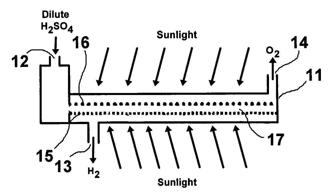
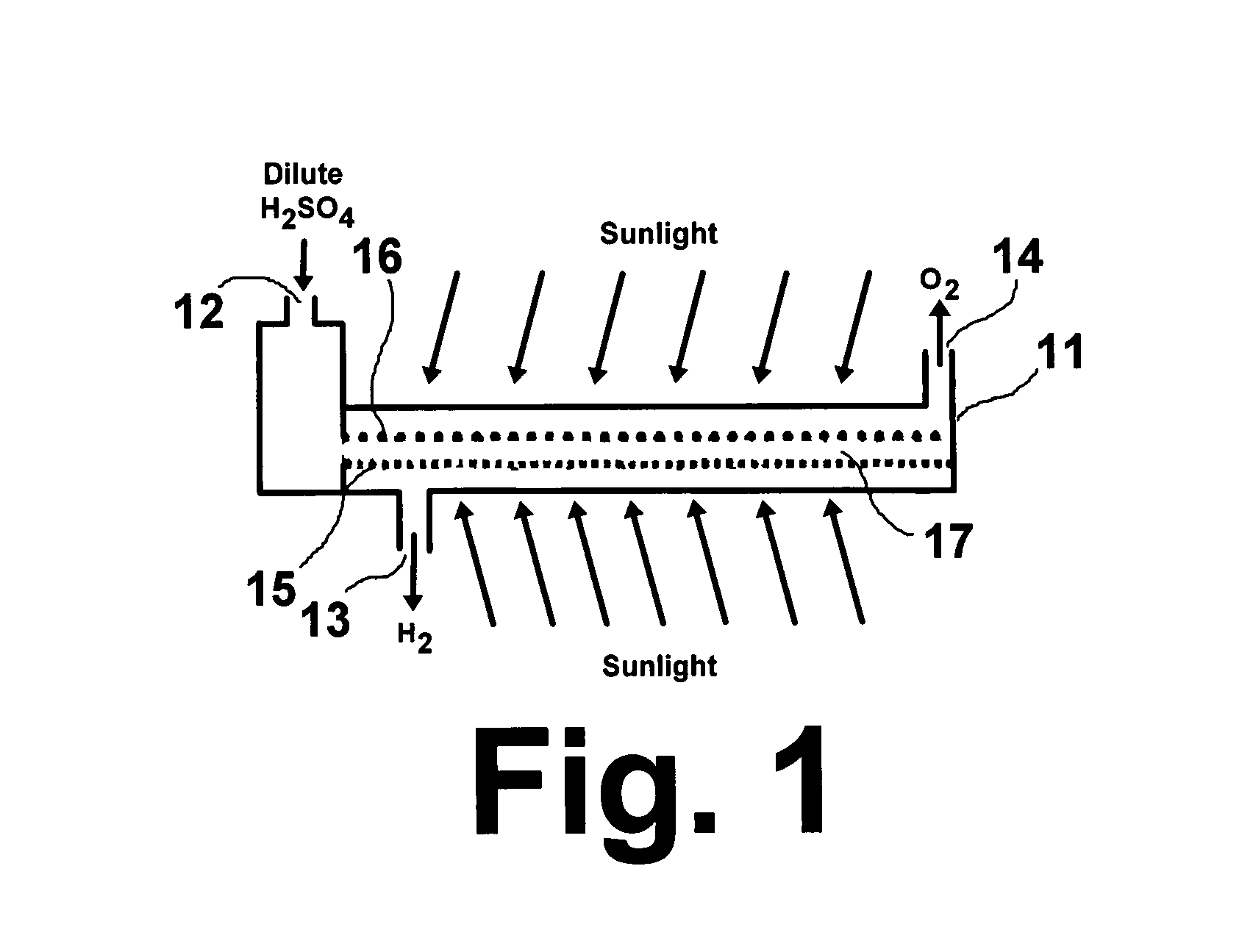
[0025]A titanium gauze (40 mesh from Alfa Aesar) was cleaned ultrasonically in distilled water, acetone, and distilled water again to remove any contaminants. The electrode was then etched in a 4 wt % concentration of HF and rinsed with distilled water. The Ti gauze electrode was used as the working electrode, a graphite rod was used as the auxiliary electrode, and a 1.0 M H2SO4 solution was used as the electrolyte with various metal salt solutions for doping metal having particle sizes in the range of about 3 nm to about 100 nm into the nano-crystalline TiO2 structure. The anode potentials were controlled at 120V for one (1) minute to obtain the TiO2 layered films interval and to −0.5V for 30 seconds for metal doping. Three cycles of oxidation and reduction processes were carried out to obtain the desired thickness and porosity. The high oxidation potential to make TiO2 produces a substantial amount of gas evolution, which generates pores in the catalyst layer. The negative voltage...


PUM

PropertyMeasurementUnit
voltageaaaaaaaaaa
current densityaaaaaaaaaa
cell voltageaaaaaaaaaa

Abstract

An apparatus for splitting water to produce hydrogen having at least one photoelectrochemical cell. The photoelectrochemical cell includes at least one water permeable photoelectrode having a light sensitive, nano-crystalline catalytic material layer, a polymer electrolyte membrane, a metallic substrate disposed between the light sensitive nano-crystalline catalytic material layer and the polymer electrolyte membrane adjacent to the polymer electrolyte membrane layer, and at least one photovoltaic device connected in series to the light sensitive nano-crystalline material layer and disposed between the light sensitive nano-crystalline catalytic material layer and the metallic substrate layer.

Description

BACKGROUND OF THE INVENTION[0001]1. Field of the Invention[0002]This invention relates to a device for producing hydrogen for portable power applications. This invention further relates to a solar-powered device for producing hydrogen for portable power applications. This invention further relates to direct photoelectrolysis of water to generate hydrogen directly with sunlight employing a combination of advances in fuel cell technology, photovoltaic technology, photoelectrochemistry, and thin film technology. Finally, this invention relates to a photoelectrode employing a nano-crystalline catalyst material for use in the photoelectrolysis of water to generate hydrogen.[0003]2. Description of Related Art[0004]Hydrogen is an important future energy carrier and energy storage medium. Efficient, low-cost methods of making hydrogen will be important elements of a future hydrogen economy. Renewable electricity integration for hydrogen production is very important for reducing greenhouse g...

Claims


Application Information

Patent Timeline
Patent Type & Authority Patents(United States)
IPC IPC(8): C25B9/08C25B9/10C25B9/17C25B9/23C25B9/19
CPCC25B1/003Y02E60/368Y10S136/291Y02P20/133C25B1/55Y02E60/36
Inventor FAN, QINBAILISS, WILLIAM E.
Owner GAS TECH INST
Why Eureka
Try Eureka