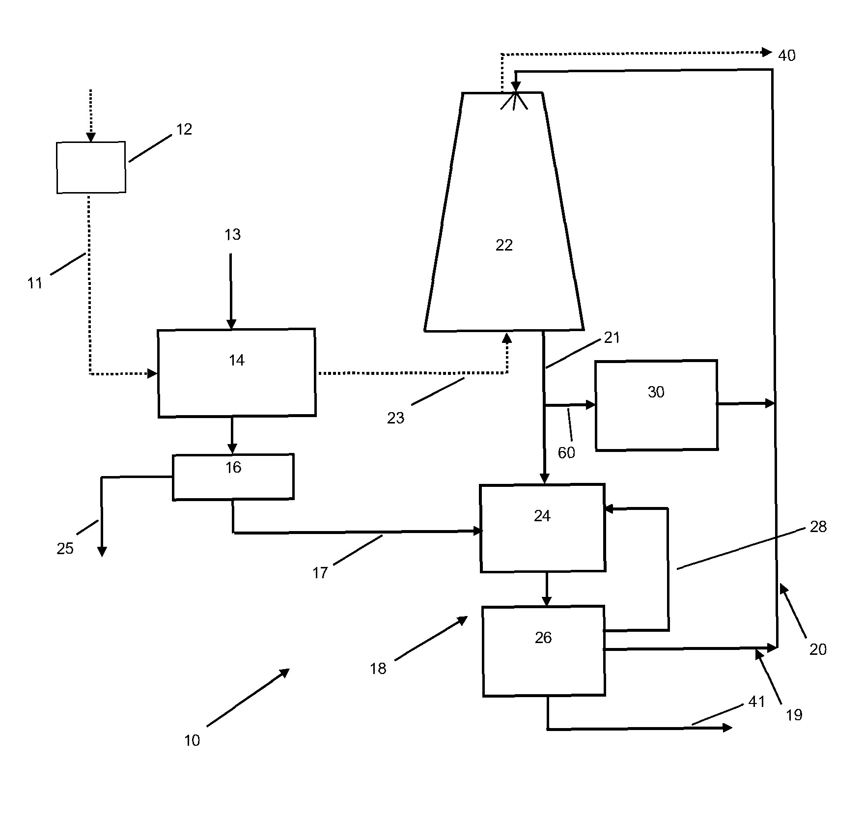
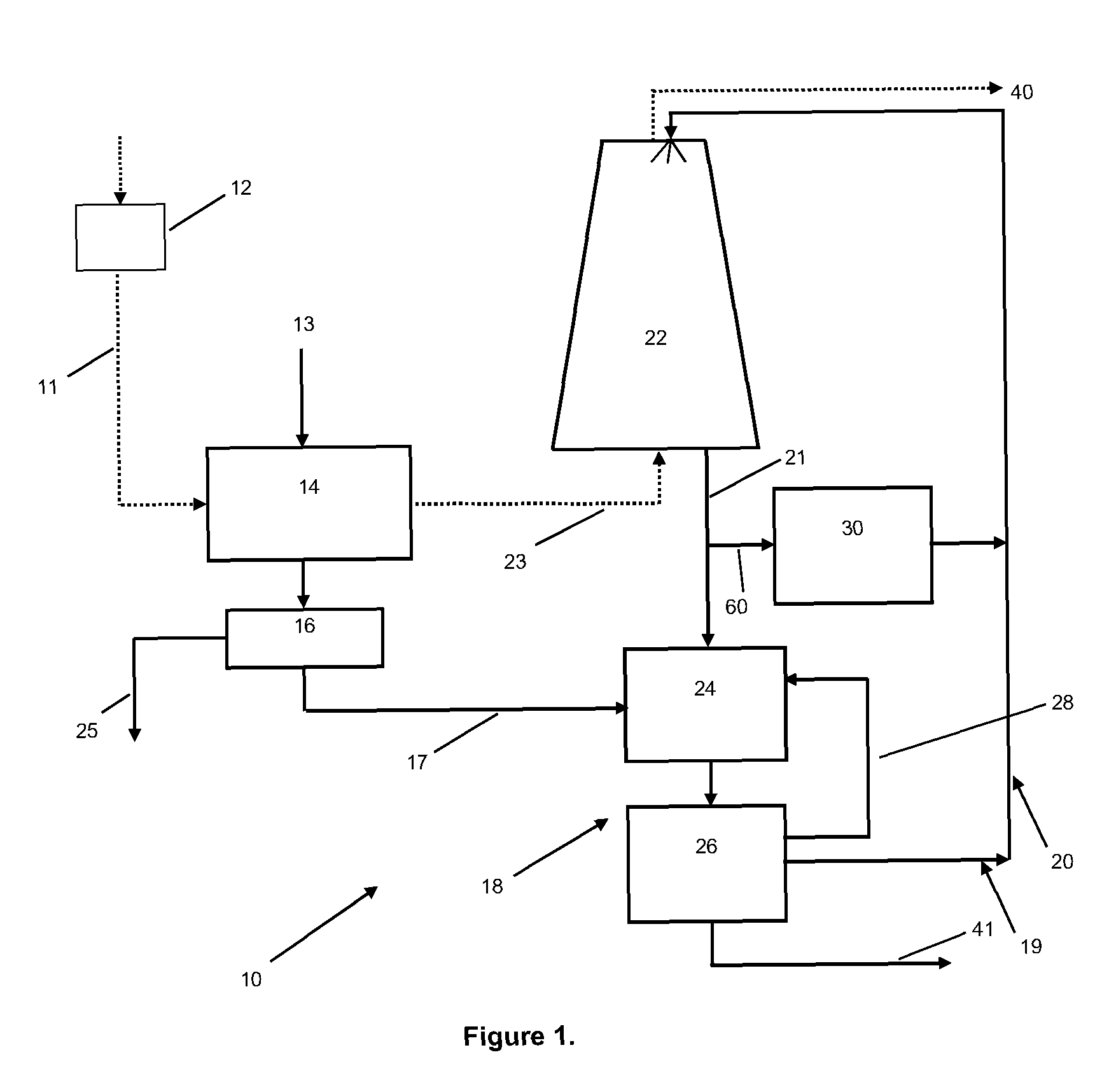
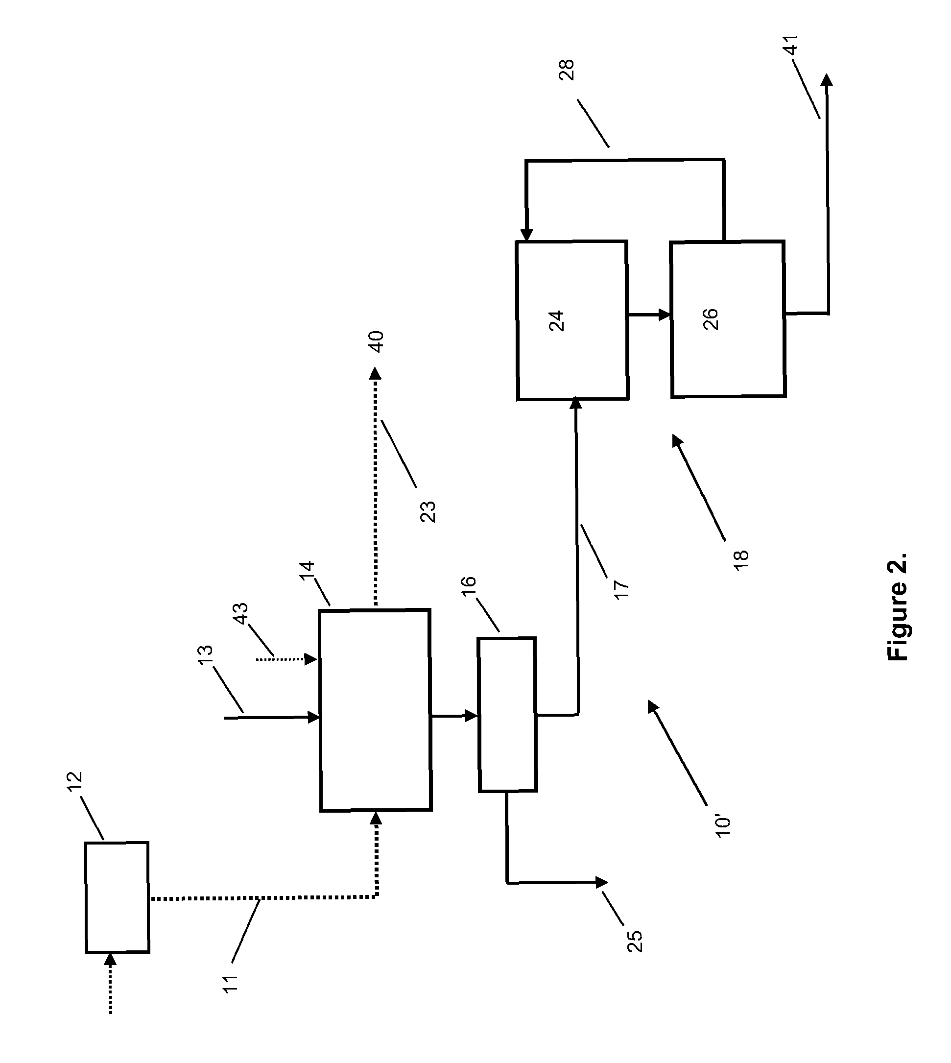
[0009]In the instant invention, the objectives of high removal of
ammonia, COS and HCN from syngas and their subsequent destruction in a cost effective, environmentally sustainable fashion is achieved by taking
advantage of the fact that, during biological
fermentation of syngas to
ethanol and / or other soluble products, some water must be purged from the
system to assist in the
wasting of excess cellular
biomass, as well as to prevent the build up of secondary metabolites and dissolved solids. For the case of converting syngas to
ethanol,
acetic acid / acetate is present in the purged water. The
acetic acid / acetate provides control of the pH in the
scrubber used to capture ammonia (and COS) and the acetate can then be used as the
electron donor for the conversion of
nitrate formed via
biological oxidation of the absorbed ammonia to N2 gas.
[0011]In the instant invention, after a preliminary step for removal of
particulates in the syngas via a separator or similar device, the
ammonia gas and COS and remaining
particulates in the syngas
stream are captured in a
scrubber. This operation concurrently cools the syngas and results in considerable condensation of
water vapor from the syngas into the scrubbing solution. The scrubbing solution added to the
scrubber is the purge water from a
fermentation process and / or still bottoms that is acidic due to the presence of an acid,
acetic acid in the case of ethanol production, in the water. This is sufficient to keep the pH in the scrubber low enough so that a high efficiency for ammonia removal can be achieved. COS is extremely soluble in water and is captured in the scrubber as well.
[0013]By using the proper amount of recycle flow from the biological treatment zone
effluent to the HCN scrubber, high efficiency of HCN removal can be achieved and the sequential anoxic-aerobic treatment steps result in high removal of the
ammonium and the
resultant nitrate produced from oxidation of the
ammonium (via reduction in the anoxic stage of the
biological process). Removal of the COS and HCN is also achieved in the anoxic step which eliminates inhibition or
toxicity that these compounds can cause on
nitrification (biological
ammonium oxidation).
Alkalinity produced via the absorption and dissociation of the ammonia to ammonium in the scrubber water combined with the additional
alkalinity produced during reduction of the
nitrate to N2 gas, using the acetate / acetic acid in the anoxic biological treatment step provides sufficient
alkalinity after the anoxic biological treatment step to buffer the water during the
ammonium oxidation or
nitrification step with little to no requirement for an
external source of
alkalinity (such as caustic). Thus the process arrangement comprises a biological treatment processor used in concert with a
water based scrubber and if desired an HCN scrubber for the high removal of ammonia, COS and HCN from syngas. The purge flow from the fermentation process supplies acetic acid to the scrubber. This helps maintain the appropriate
pH range in the scrubber water while eliminating the need for adding acid to achieve this, thus saving on cost.
[0017]The acetate / acetic acid added via the purge water in the scrubber waste water
effluent is used as both the
electron donor to reduce the nitrate to N2 gas and as the source of carbon for cellular growth of microorganisms. This eliminates the need and cost of adding an
external source for an
electron donor and
carbon source. Both COS and HCN are concurrently degraded in the anoxic biological treatment step, as well. The HCN is converted to compounds that are benign to microorganisms in the second step of the biological treatment zone, the aerobic biological treatment step. The degradation of COS and HCN is important in that these compounds have the ability to inhibit the
nitrification process if present at certain concentration levels. At least a portion of the anoxic
effluent stream passes to the aerobic biological treatment step for the nitrification of ammonium to nitrates. Afterwards, the biologically treated waste water
stream is withdrawn from the aerobic biological treatment step. A portion of the biologically treated waste water stream is internally recycled back into the anoxic biological treatment step and when HCN scrubbing is provided another portion of the biologically treated waste water stream is recycled into the HCN scrubber for contact with the HCN scrubbing water stream. The biologically treated waste water contains nitrate that is removed from the stream as it is recycled through the HCN scrubber and back into the anoxic biological treatment step in the process. The amount of biologically treated waste water internally recycled from the aerobic biological treatment step to the anoxic biological treatment step is adjusted to maintain a predetermined effluent nitrate concentration
[0019]By controlling the flow of the biologically treated waste water that is either internally recycled back to the anoxic biological treatment step from the aerobic biological treatment step or routed through an HCN scrubber the concentration of nitrate in the final biological treated waste water effluent may be controlled. Additionally, the internal recycle loop of recycling the biologically treated waste water stream directly into the anoxic biological treatment step allows the recycle rate to be decoupled from what is needed for scrubbing HCN and, therefore, better
process control of the final biological treated waste water effluent quality is achieved. If extremely stringent nitrate
discharge levels have to be met, a small
polishing anoxic biological treatment step may be added prior to
discharge.
[0020]The result is high removal of ammonia, COS and optionally HCN from the syngas (along with some
polishing of particulates) in a cost effective and environmentally benign and sustainable fashion, with the need for little to no
chemical addition.


