Porous carbon electrode with conductive polymer coating

a technology of conductive polymer coating and porous carbon, which is applied in the direction of electrochemical devices, inorganic chemistry, packaging, etc., can solve the problems of high cost limited performance, and inhibited commercial application of noble metal materials, so as to improve the capacitance performance of active materials and improve the electrode utilizing such materials

Inactive Publication Date: 2012-04-24
MAX PLANCK GESELLSCHAFT ZUR FOERDERUNG DER WISSENSCHAFTEN EV
View PDF3 Cites 24 Cited by
  • Summary
  • Abstract
  • Description
  • Claims
  • Application Information

AI Technical Summary

Benefits of technology

[0008]A principle object underlying the present invention is to enhance the capacitive per

Problems solved by technology

In EDLCs, the capacitance is proportional to the surface area of the electrode/electrolyte interface, so the performance is limited by the surface area of the electrode materials.
Although theoretically surface areas as high as 2600 m2 g−1 can be achieved for nanoporous carbon, and thus specific capacitances of 400 F g−1 can be obtained, this is not a realistic option from a cost point of view.
However, the high cost of noble metal materials inhibits their commercial application.
However, they exhibit the disadvantage of a low cycle life because swelling and shr

Method used


Image

  • Porous carbon electrode with conductive polymer coating
  • Porous carbon electrode with conductive polymer coating
  • Porous carbon electrode with conductive polymer coating

Examples


Embodiment Construction

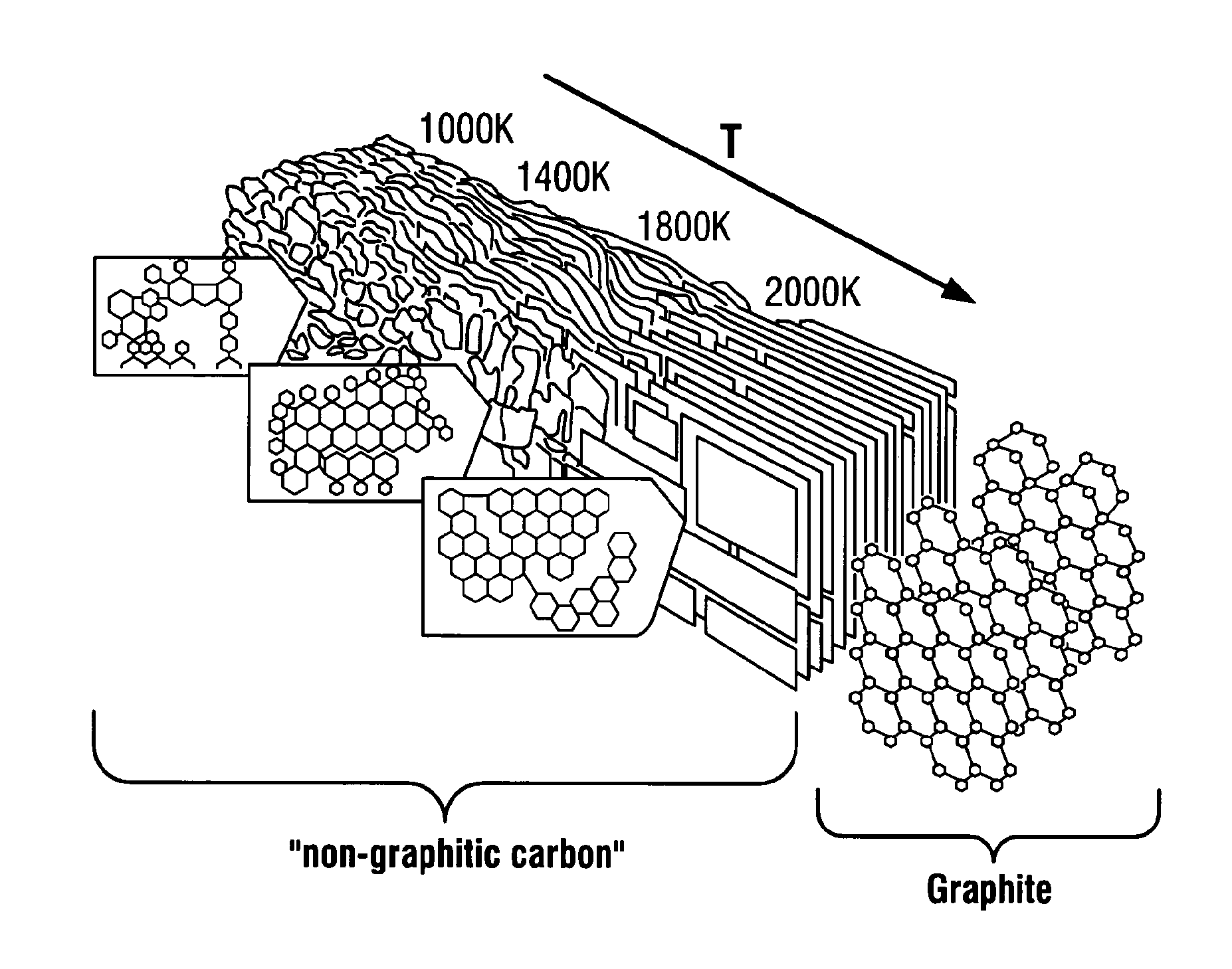
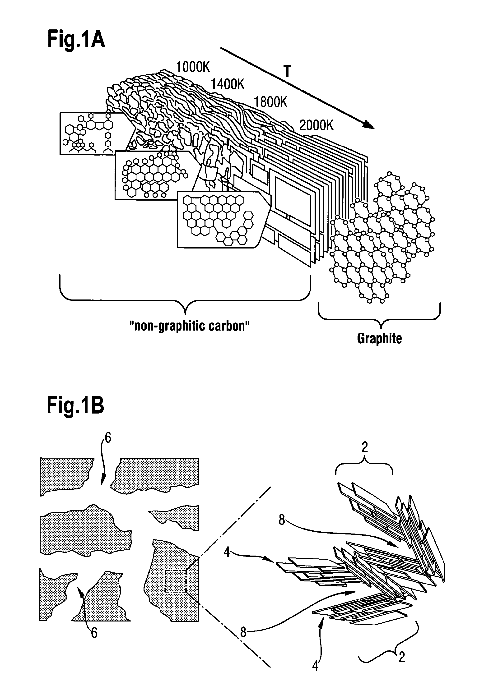
[0062]Turning first of all to FIGS. 1A and 1B, the non-graphitic carbon material underlying the present invention will first be described. FIG. 1A shows, in the diagram at the top left, how the structure of non-graphitic carbon changes as it is subjected to heat treatment (pyrolysis) at different temperatures. It can be seen from this diagram that in the temperature range of 600° C. to 1000° C. to which the present invention relates, i.e. 873 to 1273 K, the structure comprises a plurality of randomly oriented small graphene stacks 2. The stacks themselves comprise sheets 4 of carbon atoms arranged in a generally hexagonal arrangement. Each sheet 4 shown as a rectangle in FIG. 1B is termed a graphene. The carbon atoms in each graphene have no positional correlation with the position of carbon atoms in the graphenes below and above.

[0063]As the heat treatment temperature increases, the non-graphitic carbon becomes progressively more ordered and, at a temperature above 2273° K, i.e. 20...


PUM

PropertyMeasurementUnit
Temperatureaaaaaaaaaa
Pore sizeaaaaaaaaaa

Abstract

An extremely high-performance polyaniline electrode was prepared by potentiostatic deposition of aniline on hierarchically porous carbon monolith (HPCM), which was carbonized from mesophase pitch. A capacitance value of 2200 F g−1 of polyaniline was obtained at a power density of 0.47 kW kg−1 and an energy density of 300 Wh kg−1. This active material deposited on HPCM also has an advantageous high stability. These superior advantages can be attributed to the backbone role of HPCM. This method also has the advantages of not introducing any binder, thus contributing to the increase of ionic conductivity and power density. High specific capacitance, high power and energy density, high stability, and low cost of active material make it very promising for supercapacitors.

Description

CROSS REFERENCE TO RELATED APPLICATIONS[0001]This application is a National Stage of International Application No. PCT / EP2007 / 004697 filed May 25, 2007 and which claims the benefit of European Patent Applications Nos. 06011198.6, 06018886.9 and 06019348.9, the disclosures of all applications being incorporated herein by reference.BACKGROUND OF THE INVENTION[0002]The present invention relates to an electrode comprising a conductive carbon material especially for high performance applications, such as used in supercapacitors, and to methods of preparing such an electrode.[0003]Supercapacitors have attracted great interest in the energy storage field because they complement batteries with respect to energy and power densities as is described by A. S. Arico, P. Bruce, B. Scrosati, J.-M. Tarascon, W. Van Schalkwijk, in Nature Mater., 2005, 4, 366, and by R. Röz, M. Carlen, in Electrochim. Acta, 2000, 45, 2483. Supercapacitors have potential applications in hybrid transportation systems w...

Claims


Application Information

Patent Timeline
IPC IPC(8): H01G9/00H01G11/24H01G11/26H01G11/32H01G11/34H01G11/48H01G11/86H01M4/58H01M10/36
CPCC01B31/02H01G11/34H01G11/86H01M4/04H01M4/583H01M4/587H01G11/24H01G11/26H01G11/32H01G11/48Y10T428/249981Y02E60/13Y10T428/24998H01M10/0525C01B32/05Y02E60/10C01B32/00
Inventor HU, YONG-SHENGGUO, YU-GUOFAN, LIZHENMAIER, JOACHIMADELHELM, PHILIPPSMARSLY, BERNDANTONIETTI, MARKUS
Owner MAX PLANCK GESELLSCHAFT ZUR FOERDERUNG DER WISSENSCHAFTEN EV
Why Eureka
Try Eureka