Refractory material for nozzle for use in continuous casting, and continuous casting nozzle

Active Publication Date: 2012-05-08
NIPPON STEEL CORP
View PDF7 Cites 2 Cited by
  • Summary
  • Abstract
  • Description
  • Claims
  • Application Information

AI Technical Summary

Benefits of technology

[0097]In the present invention, the above advantageous effects of the hollow refractory aggregate, the specific metal and the carbon are absolutely different from those of the conventional techniques, such as a mortal-based technique, where a large volume or size of void exists from a time before initiation of receiving of molten steel, and only binding derived from resin or the like is exhibited in an initial stage of passing of molten steel, whereafter structural compression and breaking are promoted.
[0098]The bonding capability can be quantitatively expressed by bonding strength, as follows. Preferably, with respect to each of the inner bore-side layer and the outer periphery-side layer, the intermediate layer has a bonding strength of 0.01 to 1.5 MPa, as measured under a hot condition in a non-oxidation atmosphere at a temperature of 1000 to 1500° C. (temperature of molten steel). As a prerequisite to having the bonding strength, it is understood that the intermediate layer itself has a structural strength equal to or greater than the bonding strength. Thus, the following description will be made about only the bonding strength.
[0099]If the bonding strength is less than 0.01 MPa, an ability to holding the inner bore-side layer becomes lower, which is likely to cause peel-off of the inner bore-side layer, due to shock at start of passing of molten steel or a change in flow rate of molten steel, or when a local melting loss occurs in the inner bore-side layer. If the bonding strength is greater than 1.5 MPa, a strength of an internal structure of the intermediate layer is also increased to the same level as that of the bonding strength to spoil compressibility of the intermediate layer. Thus, a thermal expansion force of the inner bore-side layer is likely to be transmitted to the outer periphery-side layer without being relaxed, and particularly likely to cause splitting or cracking of the outer periphery-side layer.
[0100]The bonding strength can be evaluated as a compression shear strength S. Specifically, as shown in FIG. 2, a tubular sample having a three-layer structure in which an inner bore-side layer 2 is provided inside an outer periphery-side layer 3(4) through an intermediate layer 1 is placed on a table 8, and evenly heated under a given hot condition for a given holding time. Then, a maximum load P(N) and a displacement of the inner bore-side layer are measured while pressing only a top surface of the inner bore-side layer by a crosshead 9 moved at a speed of 0.001 to 0.1 mm / sec, and the compression shear strength S is calculated according to the following Formula 4: S(Pa)=P / A, wherein A is a bonded area (m2) of the inner bore-side layer to the intermediate layer.
[0101]A shape of the sample is not particularly limited as long as it is a tubular shape. The sample may be cut out from an actual nozzle, and subjected to the measurement. If the bonded area A is increased, the maximum load P is also increased. Thus, a maximum height dimension of the sample is preferably set to 100 mm The measurement is performed at a minimum temperature of 1000° C. and in a non-oxidation atmosphere. The reason is that 1000° C. corresponds to a temperature at which a volatile material in an organic binder is sufficiently released to complete a carbon-based binding structure so that stable compressibility and bonding capability are exhibited, and a temperature at which the reaction to deposit of the specific metal is initiated.
[0102]If the content of the specific metal in the remainder is greater than 15 mass %, the structural strength and the bonding capability of the intermediate layer are enhanced. On the other hand, the binding structure based on the metal carbide excessively increases the strength of the refractory structure of the intermediate layer, which is likely to spoil compressibility of the intermediate layer to cause difficulty in obtaining required compressibility. Moreover, the specific metal is melted during a course of temperature rise to cause a risk of flowing out from an original position in the matrix, which is likely to cause difficulty in uniformly obtaining the structural strength and the bonding force over the intermediate layer. This also leads to breakup of a part of the matrix structure and formation of an interlayer gap, and molten steel and other foreign substances are likely to intrude into a resulting void or the like. If the content of the specific metal in the remainder is less than 0.5 mass %, the effect of enhancing the structural strength of the intermediate layer and increasing the bonding strength in a non-oxidation atmosphere at 1000° C. to 0.01 MPa or more cannot be obtained, and segregation is likely to occur. Moreover, this is likely to lead to breaking or peel-off of the intermediate layer and intrusion of molten steel and other foreign substances.

Problems solved by technology

Irrespective of whether the refractory member has a single-layer structure or a multi-layer structure, such a temperature gradient gives rise to a strain due to an internal stress of the refractory member, which becomes one factor causing breaking, such as cracking in the outer periphery-side region.
Further, as the temperature gradient becomes larger, and a thermal expansion coefficient of the inner bore-side region becomes larger with respect to that of the outer periphery-side layer, a thermal stress will be increased to cause a higher risk of breaking, particularly, in the outer periphery-side region.
However, on the other hand, the increase in amount of graphite or fused silica involves deterioration in oxidation resistance and increase in reactivity with components of molten steel.
This has a disadvantage of giving rise to deterioration in durability, such as erosion (abrasion) resistance and corrosion resistance, particularly, of the inner bore-side region.
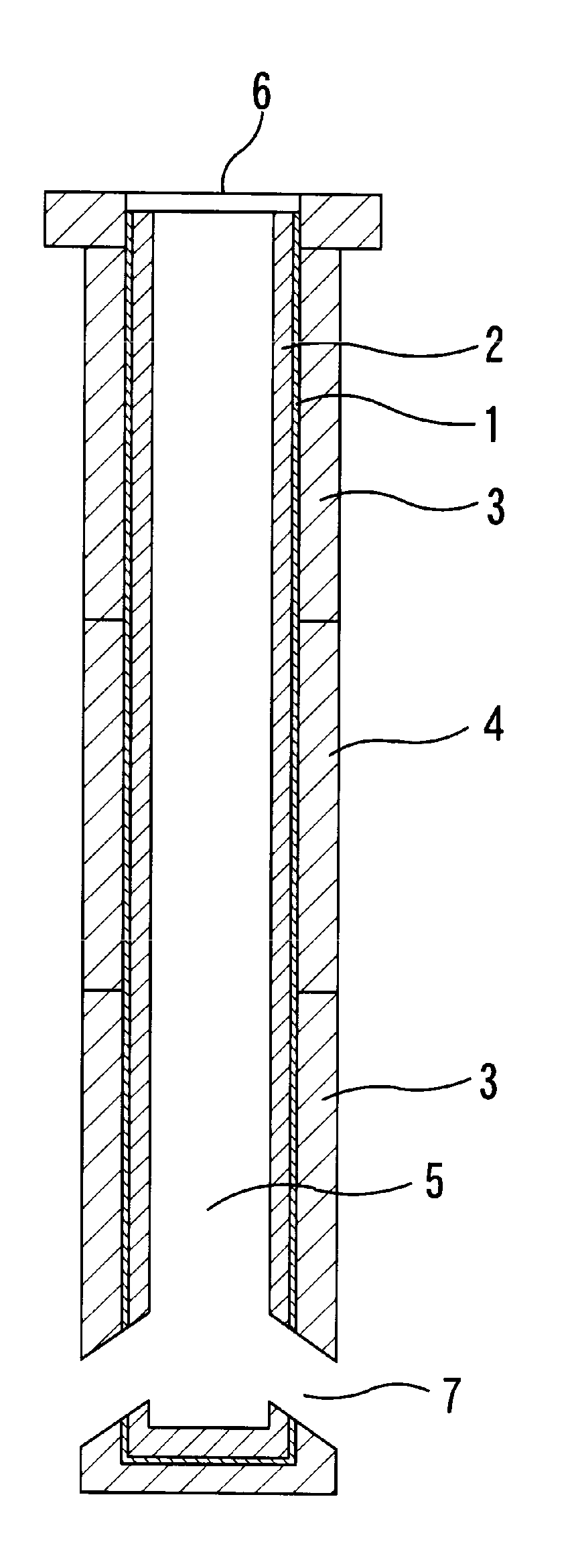
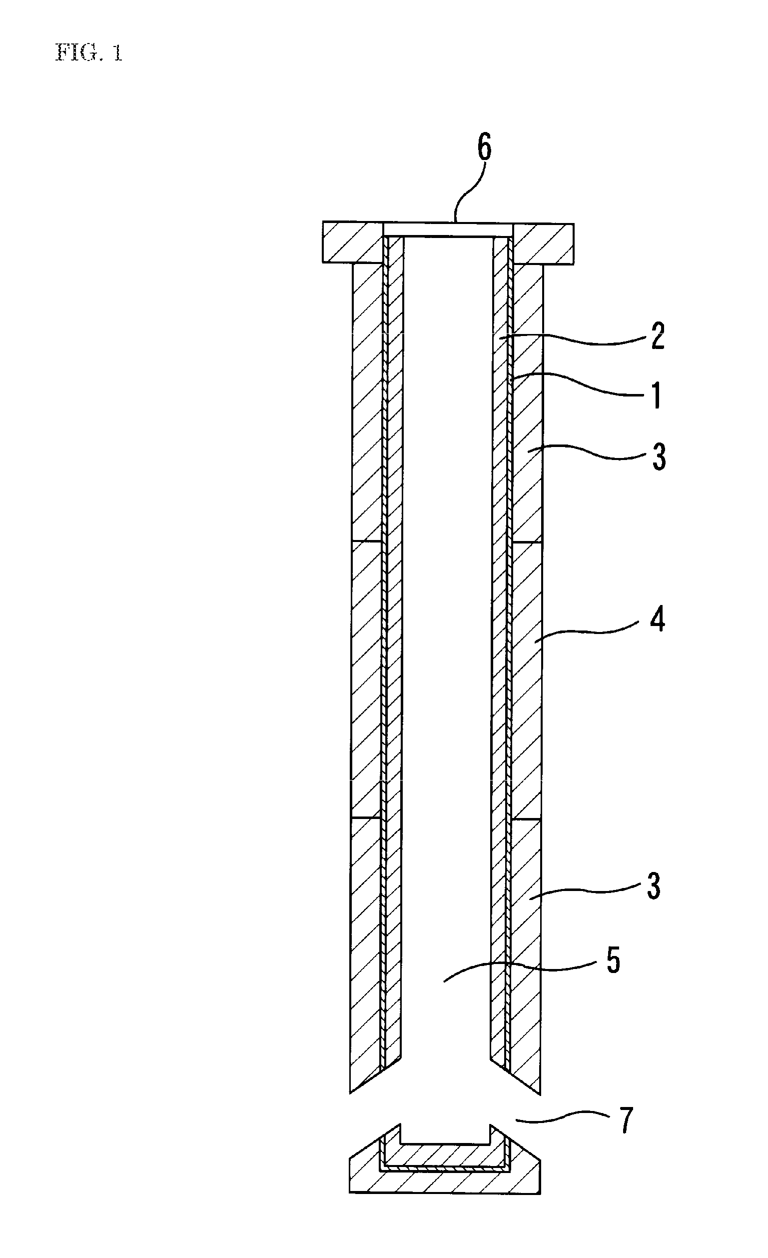
A continuous casting nozzle is used under a condition that a molten steel flow passes through an inner bore thereof, while violently colliding against an inner bore surface thereof Thus, a region of the continuous casting nozzle adjacent to the inner bore surface will be particularly severely damaged due to abrasion (erosion) caused by the molten steel, non-metal inclusions in the molten steel, etc., structural embrittlement and washing (corrosion) caused by oxidizing components of the molten steel, etc., and melting loss caused by a reaction product with FeO and other components of the molten steel.
Moreover, due to an increase in thermal gradient caused by an increase in thermal conductivity of the inner bore-side layer with respect to the outer periphery-side layer as a result of the reduction in carbon content, a difference between respective thermal expansion amounts of the inner bore-side layer and the outer periphery-side layer, and a resulting thermal stress, are apt to be more increased, which leads to a higher risk of breaking of the continuous casting nozzle, particularly, the outer periphery-side layer.
However, in the above adjustment technique, a large amount of liquid (solvent and binder) is required to obtain a high stress relaxation capability, so that the mortar is liable to have fluidity.
For example, this has a disadvantage of significant deterioration in shape retainability of the mortar to cause difficulty in ensuring a required thickness of a mortar layer or a fully filled state of the joint region.
More specifically, in an operation of installing an inner bore-side layer in a nozzle body (i.e., an outer periphery-side layer) of a continuous casting nozzle, using such mortar having a high fluidity or low shape retainability, it is highly likely that the inner bore-side layer is displaced to cause an undesirable situation where the mortar layer has a region having almost no thickness, a region having an excessively large thickness, and / or a large number of void spaces.
This situation precludes a possibility to ensure required capabilities, such as the stress relaxation capability and a capability of preventing molten steel and other foreign substances from intruding into the joint region, which leads, particularly, to breaking of the outer periphery-side layer and drop-off of the inner bore-side layer.
Thus, even if the inner bore-side layer can be fixed to the outer periphery-side layer (nozzle body of the continuous casting nozzle) in an intended relative arrangement through the mortar layer, the mortar layer is likely to be broken not only by an expansion force during stress relaxation under a hot condition but also by a weak external force during handling of the nozzle, to cause difficulty in maintaining structural stability.
This gives rise to a problem that peeling, displacement or the like of the inner bore-side layer is likely to occur.
This gives rise to another problem that molten steel, slag component and other foreign substances are infiltrated in the mortar layer through the pore (including a broken and enlarged pore) as a pathway to cause melting loss or breaking of the mortal layer itself.
Thus, the liquid is liable to be absorbed in target refractory layers to be bonded, to cause a change in concentration of a solid content of the mortar.
This means that, if each of adjacent refractory materials has a different apparent porosity, a solvent contained in the mortar to provide flexibility and bindability thereto is absorbed in the refractory materials through contact therewith, and thereby compressibility and bonding strength of the mortar are changed in each region, which gives rise to a problem that the compressibility and bonding capability become instable depending on adjacent refractory materials and a thickness of a mortar joint.
Further, during a course of the absorption and drying, the liquid is liable to cause a problem that shrinkage or crack occurs in the mortar layer itself, or gap or peeling occurs between the molar layer and each of the target refractory layers.
Moreover, along with a reduction of amount of the liquid in the mortar, aggregate particles will agglomerate together, which is likely to give rise to a problem concerning bonding capability due to a higher risk of the occurrence of crack, peeling or the like in the mortar layer.
If the bonded region is set at zero %, it causes a fundamental problem that the inner bore-side layer cannot be structurally supported.
Moreover, in the separation layer in the Patent Document 2, i.e., a so-called hollow joint, molten steel easily intrudes into a void space of the joint, which gives rise to problems, such as cracks in the refractory layers due to solidification shrinkage of the molten steel occurring when it undergoes changes in temperature and expansion of the solidified steel occurring when it is heated, and peel-off of the inner bore-side layer due to no bonding between the inner bore-side and outer periphery-side layers.
Particularly, in a continuous casting nozzle comprising an inner bore-side layer, an intermediate layer and an outer periphery-side layer, where an MgO—CaO based material is used for the inner bore-side layer, depending on respective compositions of the inner bore-side layer and the intermediate layer, a damage, such as melting / washing, is rather likely to occur beyond a bonded region where the inner bore-side layer is in direct contact with the intermediate layer, which causes problems, such as melting loss, peel-off or reduction in fixing strength of the inner bore-side layer, breakup of the intermediate layer, formation of a hollow space between the inner bore-side and outer periphery-side layers, and intrusion of molten steel into the hollow space.
However, any mortar layer having all the capabilities has not yet been obtained.[Patent Document 1] Pamphlet of International Publication No. 03 / 086684[Patent Document 2] JP 7-232249A

Method used


Image

  • Refractory material for nozzle for use in continuous casting, and continuous casting nozzle
  • Refractory material for nozzle for use in continuous casting, and continuous casting nozzle
  • Refractory material for nozzle for use in continuous casting, and continuous casting nozzle

Examples


example

[0170]Various examples will be described below.

example a

[0171]Example A is a result of a test for checking an influence of an average radius R of each particle of a hollow refractory aggregate and a ratio of the average radius R to an average wall thickness t of the particle (R / t) on breaking of the hollow refractory aggregate when an external force of 2.5 MPa is applied thereto.

[0172]Table 1 shows a material / structure and a test result of each sample in Example A.

[0173]

TABLE 1ComparativeInventiveInventiveInventiveComparativeInventiveInventivesample 1sample 1sample 2sample 3sample 2sample 4sample 5Material of hollow refractory aggregatealumina-silicate based materialAverage radius Rμm2.52.52.535250250250Average wall thickness tμm1.30.250.21312510Ratio (R / t)1.91012.53581025Breakup rate in container during vertical%9598999099compression by 2.5 MPa

[0174]A hollow refractory aggregate for test samples was obtained by selecting one of available products generally sold on the market, dispersing particles thereof in water, collecting floated one...

example b

[0180]Example B is a result of a test for checking an influence of a volume percentage of a hollow refractory aggregate with respect to a refractory material, on a compressibility and a bonding strength, and a result of a simulation test for casting of molten steel based on inner-bore heating.

[0181]Table 2 shows a composition and a test result of each sample in Example B.

[0182]

TABLE 2ComparativeComparativeComparativeInventiveInventivesample 3sample 4sample 5sample 6sample 7Hollow refractory aggregatevolume %0581025Reminder (matrix)volume %10095929075Mixing rate in remainder (100) *1Graphite fine powder (45 μm or less)mass %7575757575Al—Mg alloy (45 μm or less)mass %1010101010MgO fine powder (45 μm or less)mass %1010101010Phenol solution (as C)mass %55555Rate of carbon in remaindermass %8080808080Compressive rate (to 2.5 MPa) at 1000° C.%3461228Compressive rate (to 2.5 MPa) at 1500° C.%2351026Bonding strength at 1000° C.MPa4.002.902.101.501.00Bonding strength at 1500° C.MPa2.602.101....


PUM

PropertyMeasurementUnit
temperatureaaaaaaaaaa
pressureaaaaaaaaaa

Abstract

In a insert-type continuous casting nozzle comprising a highly functional layer formed to have a high corrosion resistance, a high anti-attachment capability, etc., and provided to define an inner bore thereof, the present invention is directed to providing a refractory material (mortar) for an intermediate layer of the continuous casting nozzle, which has a property capable of fixing an inner bore-side layer to an outer periphery-side layer (a nozzle body) of the continuous casting nozzle, while preventing the occurrence of expansion splitting in the outer periphery-side layer due to a difference in thermal expansion between the inner bore-side and outer periphery-side layers, and a continuous casting nozzle using the refractory material for the intermediate layer. The refractory material for the intermediate layer contains a hollow refractory aggregate in an amount of 10 to 75 volume %, wherein a ratio of an average radius R of each particle of the aggregate to an average wall thickness t of the particle satisfies the following relation: R / t≧10. This refractory material is disposed between an inner bore-side layer (2) and an outer periphery-side layer (3, 4) of a continuous casting nozzle.

Description

TECHNICAL FIELD[0001]The present invention relates to a continuous casting nozzle comprising an outer periphery-side layer and an inner bore-side layer having a thermal expansibility greater than that of the outer periphery-side layer, wherein the inner bore-side layer is disposed to define an inner bore surface for contact with molten steel.[0002]In the present invention, the term “inner bore-side layer” collectively means any refractory layer located on the side of an inner bore of a continuous casting nozzle relative to an intermediate layer in a horizontal cross-section taken at any position of an overall length of the continuous casting nozzle oriented in a molten-steel passing direction (i.e., vertical direction), and covers any layer structure. For example, the inner bore-side layer may be made up of a plurality of layers. In this case, the term “thermal expansion coefficient of the inner bore-side layer” means a maximum one of respective thermal expansion coefficients of the...

Claims


Application Information

Patent Timeline
Patent Type & Authority Patents(United States)
IPC IPC(8): B22D41/50
CPCB22D41/54C04B35/013C04B35/0435C04B35/057C04B35/18C04B35/66C03C11/002C04B2235/5436C04B2235/3201C04B2235/3206C04B2235/3208C04B2235/3418C04B2235/36C04B2235/401C04B2235/402C04B2235/425B22D11/10B22D41/50
Inventor MORIKAWA, KATSUMISASAKI, AKINARIHIRAIWA, YOSHITAKANEBA, KEIICHIROSADANO, TAKASHIFUKUNAGA, SHINICHITANAKA, KAZUHISA
Owner NIPPON STEEL CORP
Why Eureka
Try Eureka