Comprehensive method for local application and local repair of thermal barrier coatings

a thermal barrier coating and local application technology, applied in the direction of superimposed coating process, machines/engines, other domestic objects, etc., can solve the problems of localized loss of tbc layer, insufficient quality of coating, transport and installation damage, etc., to improve the strain tolerance of the repaired location, reduce shrinkage, and reduce shrinkage

Inactive Publication Date: 2012-07-17
ANSALDO ENERGIA IP UK LTD
View PDF18 Cites 47 Cited by
  • Summary
  • Abstract
  • Description
  • Claims
  • Application Information

AI Technical Summary

Benefits of technology

[0068]The preferred embodiment can satisfy the need of a comprehensive assessment of coatings with appropriate techniques and a local repair method for coatings on components for gas turbines and heat engines. It provides a local repair method, which overcomes prior art disadvantages, such as too low achievable thickness and too high shrinkage of the repaired zone. It also enables a repair on-site and in a mounted condition of the component.
[0069]In these preferred embodiments of the invention, the method can also overcome a lack in the prior art for assessment of the coatings. In particular, an approach for sequenced inspection with appropriate methods can locate deteriorated areas of the coating prior to repair and improve the reliability of the repair.
[0078]According to a further preferred embodiment of the proposed method, after the local application of a patch, a pattern is induced on or in the applied coating material while it is not yet solidified. In principle, in view of the composite nature of the patches produced, crack formation is essentially prevented. Nevertheless, due to large strains, cracks may have the tendency to form, the corresponding indentations or grooves of the pattern in the surface of the layer in these regions, if at all, during solidification but also during subsequent use of the coating lead to a controlled minimum crack formation so the generation of large cracks can essentially be prevented. The induction of the pattern can be done mechanically by way of scratching, imprinting, screening, cutting, and can be done thermally and / or chemically. Possible patterns are rectangular or triangular or more generally polygonal normally regular grid patterns, preferably the pattern is a honeycomb type pattern.

Problems solved by technology

During operation the BC / TBC system has to sustain thermal cycling and harsh environmental conditions.
Also to be considered are damages due to transport and installation as well as insufficient quality of the coating as produced in the workshop.
As a result, localized loss of the TBC layer can occur, e.g., due to foreign object impacts, phase changes, and fatigue, but also sintering of the ceramic and erosive wear, particularly on highly loaded locations of components.
Health and safety issues, cost and technology status of portable devices are boundary conditions, which prevent the use of spray techniques for local application such as repair on-site.
Further disadvantages are the accessibility of the components when mounted in the engine and contamination of the hot engine parts in the vicinity of the local application spot due to the local application process.
One challenge is to coat a layer with an adapted and sufficient thickness, which is at least equivalent to the one of the original TBC.
Sol-gel techniques, as for example described in U.S. Pat. No. 6,235,352, ensure a good bonding of the newly constituted layer but lead generally to an insufficient layer thickness.
Another relevant concern by using wet chemical processing is that during drying and curing the applied layer has a pronounced tendency to shrink leading to cracks, bonding defects and spallation.
Another issue with the wet chemical processing is to achieve a suitable viscosity in order to coat parts with a complex geometry or in order to coat parts mounted inside the engine (in particular if the surface to be treated is in a vertical position or is facing downwards).
This is a costly and time consuming process.
Furthermore, a comprehensive inspection for different defect types is not considered in the prior art.
Particularly, it is missing that inspection has to be performed prior to repair with appropriate tools in order to locate all degraded areas of the BC / TBC system and in order to only locally repair where it is necessary and appropriate.
For example, it is not sufficient just to clean regions with spalled-off TBC, as described for instance in U.S. Patent Application Publication No. 2007 / 0202269 A1.
Further the reachable layer thickness by pure wet application methods is in general limited and usually a high shrinkage of the applied coating leads to macrocracking as well as weak bonding of the coating to the substrate due to the shrinkage, and the strain tolerance of the suggested coating systems is in general not sufficient.
Usually, the thermal barrier effect of the applied coating is not sufficient, complex shapes (convex / concave) are difficult if not impossible to repair with approaches mentioned in prior art, and the same is valid for coating application in a vertical position of the component.
The stability of the wet applied coatings against high temperature and repeated temperature changes (thermal cycling) in general not sufficient.
However, the coating might be already suffering from pre-damages like delaminations of the TBC from BC, macrocracks within TBC or BC, or sintering of the TBC, which can finally lead to spallation.
Other degradation marks of the coating system, which have to be taken into account, are erosion of the TBC, and consumption, oxidation, corrosion of bond coat and base material.
Another issue is the inspection of the repaired locations at the end of the process.
As it is possible that the restoration of the TBC is not successful (even if not visible), a final inspection and / or intermediate inspection, in the case of multi-step repair, of the component is necessary.
Furthermore, during the application of subsequent layers, cracks, which have formed in an underlying layer, will be filled by material of the subsequent layer.

Method used


Image

  • Comprehensive method for local application and local repair of thermal barrier coatings
  • Comprehensive method for local application and local repair of thermal barrier coatings
  • Comprehensive method for local application and local repair of thermal barrier coatings

Examples


example 1

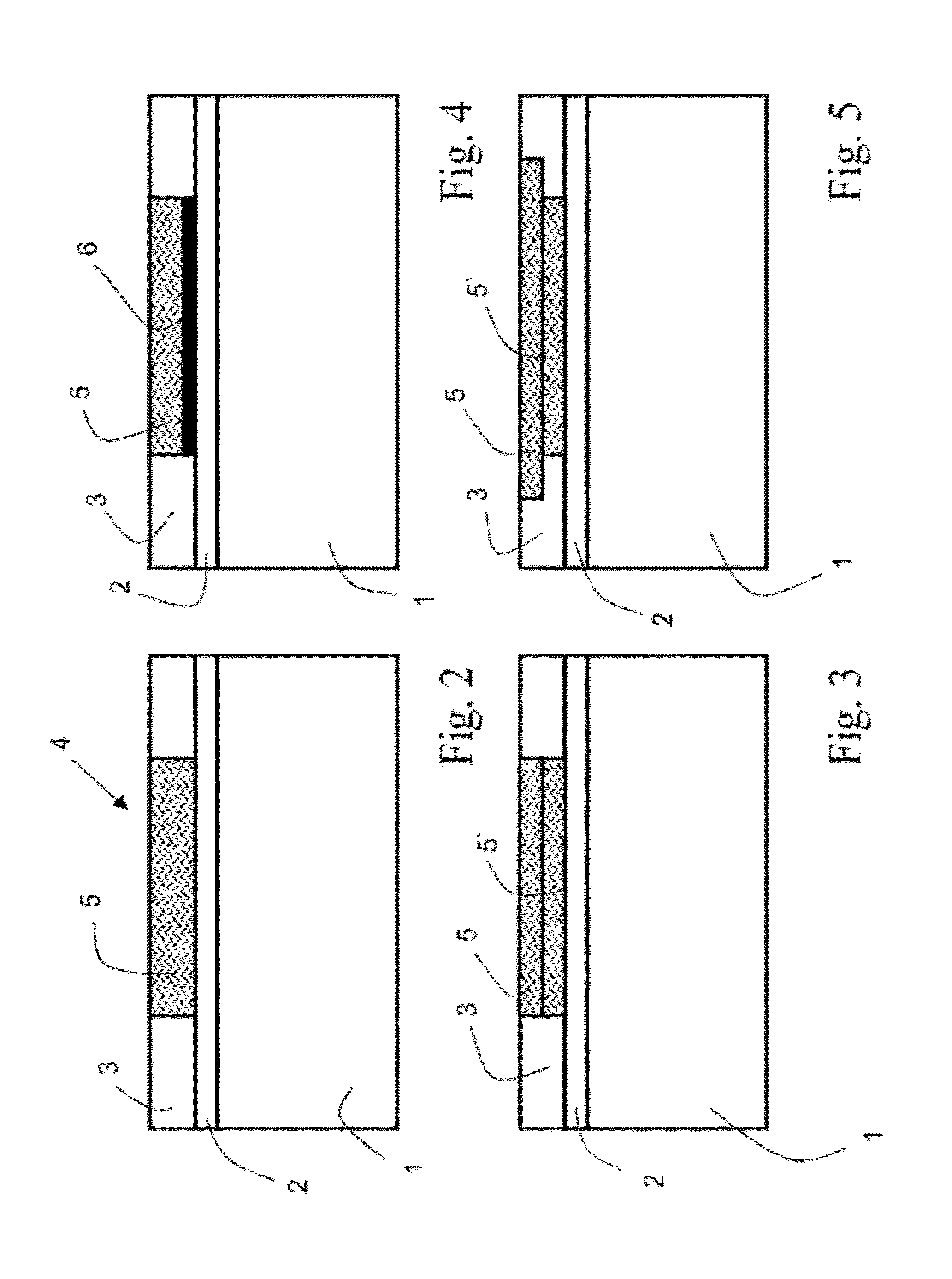
[0169]A coating patch as described above was fabricated on top of a sample made from a Ni-based alloy. Surface preparation in this specific situation was not performed since it was not necessarily, as the alloy was already coated with an oxidation resistant overlay coating providing a rough surface. After cleaning, as a first step a thin layer of ceramic slurry was applied to the surface. Subsequently and after application, a flexible ceramic tissue (Woven Knit Cloth, supplied by Zircar Zirconia, Inc.) of an adapted size was attached on top of the still-liquid slurry leading to an infiltration of at least the lower part of the tissue. After drying and curing using a hot air fan, an intermediate inspection step was carried out to check the adhesion of the composite layer to the substrate. In the second coating cycle a thin layer of ceramic slurry was applied onto the ceramic tissue again leading to an infiltration of at least the upper part and therefore a stabilization of the cerami...

example 2

[0173]The same method as described above under example 1 was used for making a patch of a barrier coating. In this second example, after application of each layer, the layer was structured using a honeycomb surface imprinting with an approximately 3 mm honeycomb cell size. For the structuring of the surface, a honeycomb pattern was imprinted into the surface by rolling a specifically structured tool over the ceramic slurry layer such that a pattern of grooves was generated with a penetration depth of the generated grooves of approximately 50 μm. The generated pattern was shifted for each subsequent layer, so the generated grooves of the subsequent layers were staggered with respect to each other (see also FIG. 9).

[0174]The resulting coating structure in the patch region was free of cracks and attached well to the underlying structure.


PUM

PropertyMeasurementUnit
honeycomb cell sizeaaaaaaaaaa
penetration depthaaaaaaaaaa
structureaaaaaaaaaa

Abstract

A method for the local initial application of a thermal barrier coating layer (3), or for the local repair of coating defects and / or deteriorations of components (1) in the hot gas path of a gas turbine engine, which components are coated with a thermal barrier coating layer, includes at least the following steps:(I) in the case of repair, normally overall inspection of the whole component (1) for the determination of the location of defect / deterioration, as well as of corresponding type of defect / deterioration of each place for a multitude of locations of the component (1);(II) if needed, preparation of the surface in at least one location;(III) local application of a ceramic tissue together with a wet chemical thermal barrier coating layer deposition material for the formation of a patch (5) of ceramic matrix composite;(IV)a intermediate inspection of the patch and / or the surface;(IV)b in the case of a repetitive and / or multi-step repair method, subsequent layer application of a ceramic tissue together with a wet chemical thermal barrier coating layer deposition material for the formation of a patch (5) of ceramic matrix composite at this location;(V) if needed, surface finishing at the at least one location; and(VI) final inspection of the at least one location.Steps (IV)a, (V) and (VI) can be omitted with the provision that at least one of steps (IV)a or (VI) is carried out.

Description

[0001]This application claims priority under 35 U.S.C. §119 to European application no. 09156600.0, filed 30 Mar. 2009, the entirety of which is incorporated by reference herein.BACKGROUND[0002]1. Field of Endeavor[0003]The present invention relates to the field of methods for the manufacturing and the service of components in the hot gas path of, for example, gas turbines. Specifically, it relates to a method of improved localized build-up of thermal barrier coatings (TBC) on hot gas path parts in gas turbines and other heat engines combined with a comprehensive approach of inspection to better assure the durability of the coating.[0004]2. Brief Description of the Related Art[0005]Coating systems for hot gas path (HGP) parts of gas turbine engines for the protection of components are well known. Many of these coating systems consist of a metallic bond coat (BC) layer and a ceramic thermal barrier coating (TBC) top layer. The TBC layer is predominantly applied to protect the base ma...

Claims


Application Information

Patent Timeline
Patent Type & Authority Patents(United States)
IPC IPC(8): C03B29/00C04B33/34B41N1/24B05C13/00B32B43/00B05D3/00C23C16/52
CPCC23C24/00F01D5/005C23C28/322C23C28/3455C23C28/042F05D2260/80F05D2230/30C23C24/08
Inventor REITZ, DANIELDUVAL, SOPHIEGRASSO, PIERO-DANIELESTANKOWSKI, ALEXANDERSANTOS SILVERIO, FERNANDO MANUEL
Owner ANSALDO ENERGIA IP UK LTD
Why Eureka
Try Eureka