Method of producing particles by physical vapor deposition in an ionic liquid

a technology of ionic liquid and physical vapor deposition, applied in the direction of metal/metal-oxide/metal-hydroxide catalyst, chemical/physical process, conductive materials, etc., can solve the problems of difficult or hazardous work, and not being able to meet the requirements of the work environmen

Active Publication Date: 2013-01-15
VITRO FLAT GLASS LLC
View PDF9 Cites 2 Cited by
  • Summary
  • Abstract
  • Description
  • Claims
  • Application Information

AI Technical Summary

Benefits of technology

[0029]It was found in the present invention that when a vapor produced by physical vapor deposition (PVD) was deposited over an IL in a vacuum system, nanoparticles were produced and that ionic liquids acted as stable reservoirs for the particles. Magnetron sputtering was the method used to deposit the vapor in the following examples. However, any physical deposition process carried out in a vacuum system can be used to produce particles. An advantage of the invention over the known art is the capability of containing a liquid in a vacuum system, wherein the liquid has negligible effect on the pressure in the system. The low base and deposition pressures required for vacuum coating processes are achieved as if there were no liquid present in the system. Another advantage of an IL is that it is a universal solvent that lends itself to chemical processing (see AIChE Journal, (November 2001) Vol. 47, pages 2384-2389 for IL's in Chemical Processing). The nanoparticles of the invention are incorporated into an IL, thus eliminating steps for transfer into a medium for further processing and / or eliminating multi-step chemical processing steps. Additionally, it has been shown that the volume of the deposited particle is proportional to the deposition pressure, thus a lower deposition pressure is ideally suited not only for running a stable process free from contamination, but also for consistently and reliably producing particles within a desired particle size range, e.g. a nanoparticle size range. As used herein, “particle” or “nanoparticle size range” means particles having a maximum dimension of no greater than 500 nm, such as no greater than 200 nm, e.g. no greater than 100 nm, or no greater than 50 nm, or no greater than 10 nm, such as in the range of 0.1 nm to 200 nm, such as in the range of 0.5 nm to 200 nm, such as in the range of 1 nm to 200 nm. The deposition process is carried out at pressures of no greater than 50 microns of Hg, for example no greater than 20 microns of Hg, such as no greater than 10 microns of Hg, such as no greater than 7 microns of Hg, or no greater than 5 microns of Hg, such as no greater than 4 microns of Hg, such as no greater than 3 microns of Hg, or no greater than 2 microns of Hg, such as no greater than 1 micron of Hg. As will be appreciated, one micron is equivalent to 0.001 Torr. In addition, the IL does not require any additives that will increase the vapor pressure, to prevent particle agglomeration, and limit the capability of the process to run at low pressure. Additives that increase the viscosity but do not affect the vapor pressure can also be utilized. ILs of different viscosities can be mixed to adjust the viscosity of the final liquid.
[0030]The following non-limiting examples illustrate various aspects of the invention. In these examples, copper, silver, and tungsten oxide were sputtered deposited on the ionic liquid in a vacuum system. The vacuum system base pressure, which was in the range of 10−6 to 10−7 torr, did not change appreciably differently than a conventional solid substrate after the liquid was introduced, accounting for the negligible vapor pressure of ionic liquids. This also enabled the deposition at pressures of 7 microns of Hg or less. There was no change in pressure during deposition. Nanoparticles were formed in the liquid as a result of the deposition into the liquid.
[0031]To illustrate the invention, the method of making and characterizing several of the materials are described in detail below. Samples were prepared by wetting the surface of a clear float glass substrate with an ionic liquid (IL) using an eyedropper to cover about 1.5 inches (3.8 cm) square to a depth of less than a millimeter. A spatula was used to aid in spreading the liquid over the surface. The glass substrate containing the IL was 3 inches (7.6 cm) square. The substrate was then placed on a carrier plate, placed in the entry lock of an Airco Temescal ILS 1600 vacuum coater, and evacuated before entry into the deposition chamber, which was set at a base pressure of less than 10−6 torr. All coatings were deposited by DC magnetron sputtering between the pressures of 1 and 7 microns of Hg. The substrate moved under the sputtering target as a speed of 120 inches / min (3 m / min). There was no change in pressure after the sample containing the IL entered the chamber, or during the deposition process. The coating thickness was measured using a Tencor P1 stylus profilometer unless otherwise indicated.

Problems solved by technology

A bulk material should have constant physical properties regardless of its size, but at the nano-scale this is often not the case.
While adequate for forming nanoparticles, these current solution chemical processes do have some drawbacks.
In addition, some of the reagents required may be harmful to workers and thus difficult or hazardous to work with.

Method used


Image

  • Method of producing particles by physical vapor deposition in an ionic liquid
  • Method of producing particles by physical vapor deposition in an ionic liquid
  • Method of producing particles by physical vapor deposition in an ionic liquid

Examples


example 1

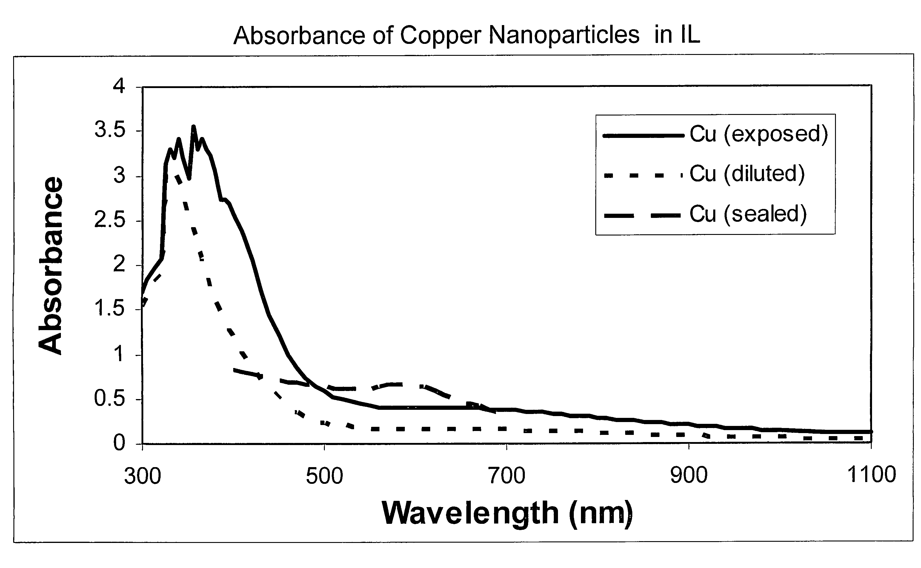
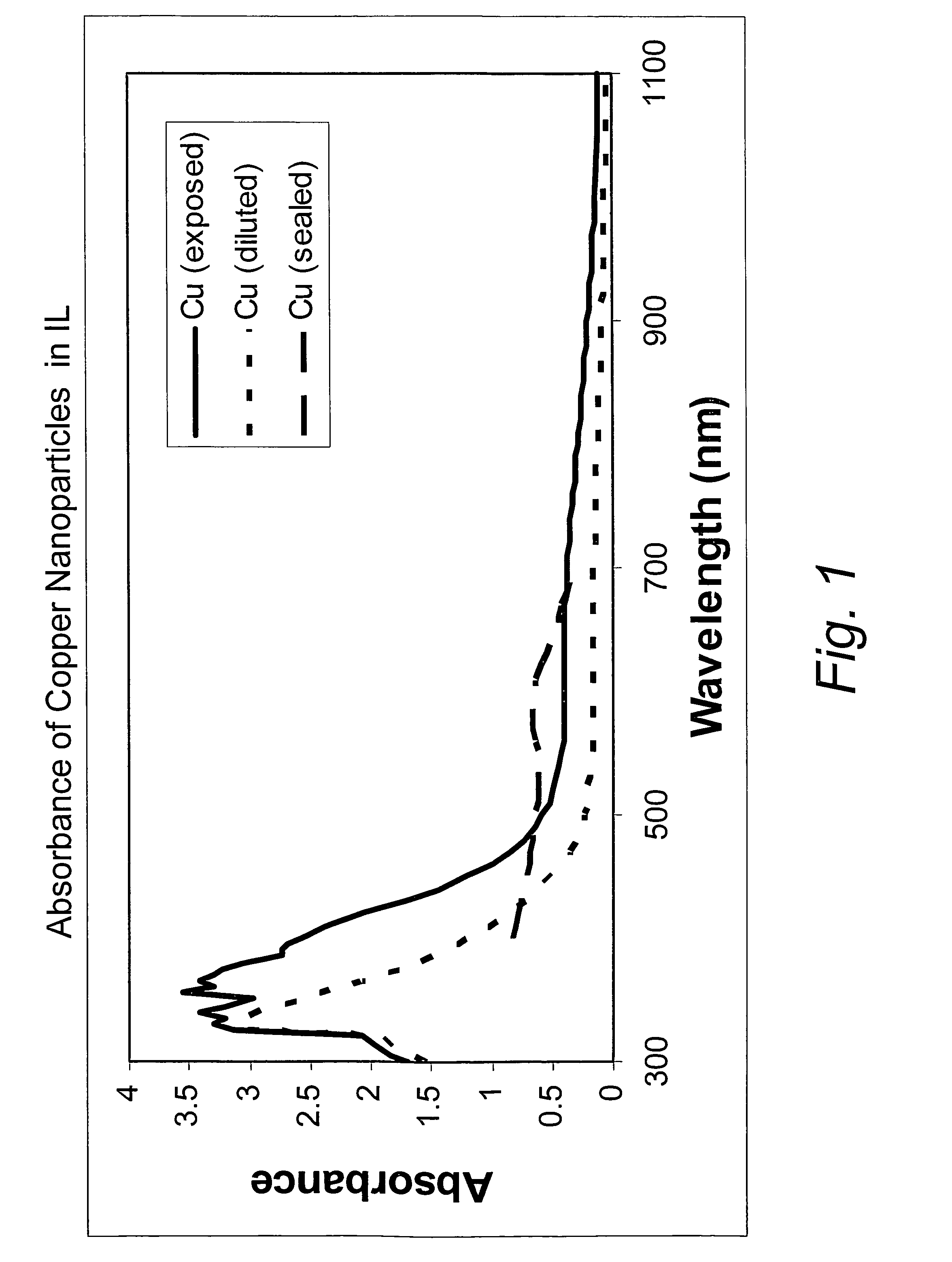
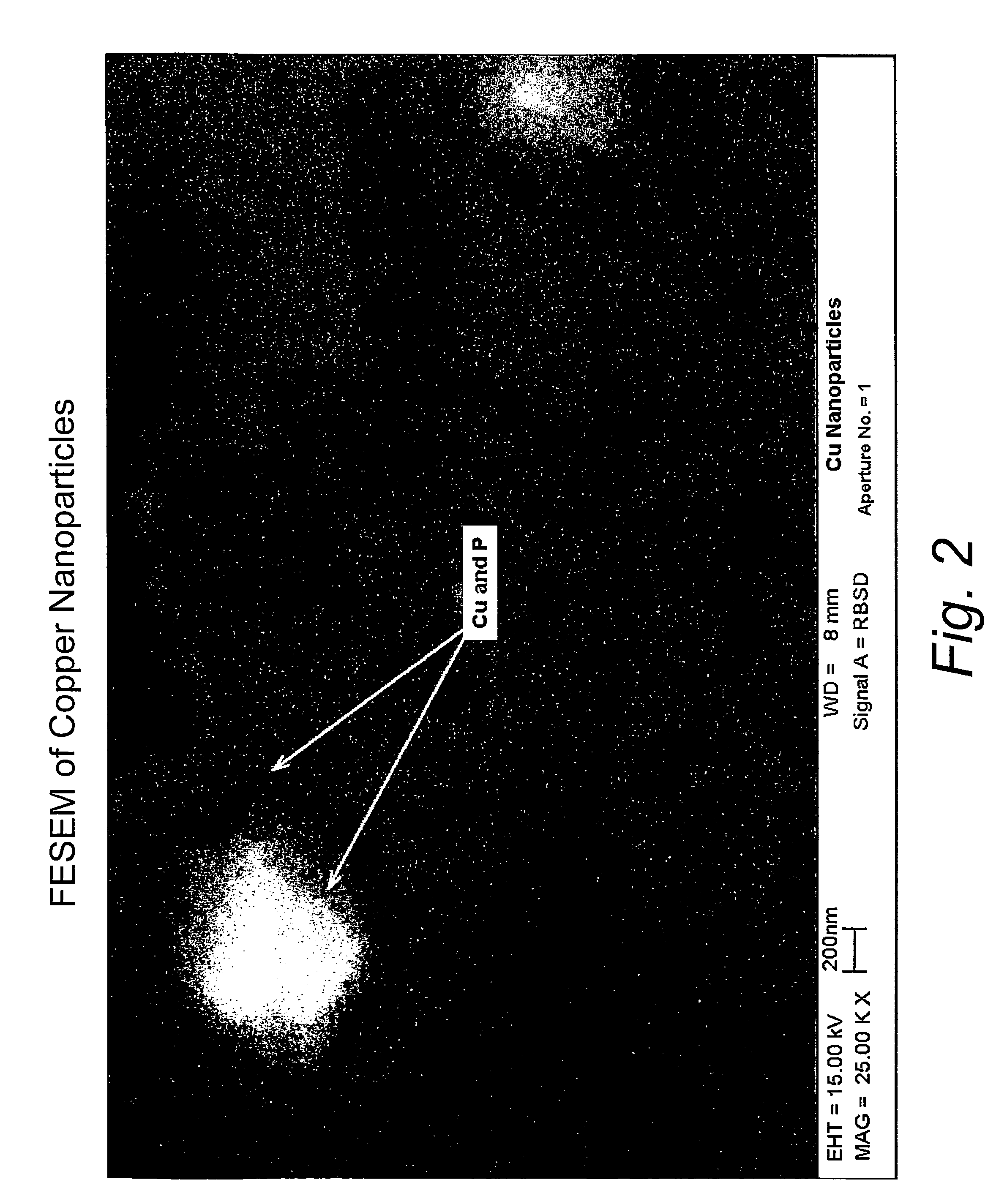
[0032]This example illustrates the formation of copper nanoparticles. Copper was deposited from a copper target at a constant power of 1.5 kW, a voltage of 508 volts, and a current of 2.95 amps in an argon gas atmosphere at a pressure of 4 microns of Hg. The substrate passed under the target 20 times. After deposition, the sample was removed from the chamber. The area of the glass surface surrounding the ionic liquid ([BMIM]PF6 described above) was covered with a copper film, as expected. The IL, however, appeared unchanged, except for a transmitted color that appeared reddish-brown in color, and which developed a greenish component after about 4 minutes. If the copper containing IL were left in the coater under vacuum for at least 4 minutes, and then removed, the IL was the reddish-brown color without the greenish hue. However, the hue developed after about 4 minutes, as previously described. If the sample was covered with glass plate upon removal from the coater, the solution rema...

example 2

[0040]This example illustrates the formation of silver nanoparticles. Silver was deposited in a manner similar to the method described in Example 1 for copper. The silver was deposited at a constant power of 3.0 kW, a voltage of 599 volts, and 5.0 amps in an argon gas atmosphere at a pressure of 4 microns of Hg. The substrate passed under a silver target 10 times. The silver containing IL was removed from glass substrate by rinsing in acetone into a collection dish. The silver film thickness was 463 nm as measured at the boundary between the film and the uncoated area that contained the IL. This is equivalent to about 470 μg per square cm of silver as calculated from the density derived from XRF measurements for sputtered silver films. The particle removal was performed by diluting the silver containing IL in the dish several additional times with acetone, removing acetone and IL after each dilution with filter paper. The acetone was then allowed to evaporate until a film of agglome...

example 3

[0044]This example illustrates the formation of tungsten oxide nanoparticles. Tungsten oxide was deposited in a method described above. A tungsten target was deposited in a reactive gas atmosphere of 50% O2 and 50% Ar by flow at a pressure of 4 microns of Hg. The target was run at a constant power of 3.0 kW, a voltage of 486 volts, and a current of 6.24 amps. The substrate passed under a target 10 times. The tungsten oxide containing IL was removed from glass substrate by rinsing in acetone into a collection dish. The tungsten oxide was 117 nm thick (as determined in the manner discussed above). The tungsten oxide containing IL had a yellow appearance when viewed in transmittance. It is believed that this coloration is due to either the presence of tungsten oxide in the IL or a reaction of the plasma with the IL. The particle removal was performed by initially diluting the tungsten oxide containing IL in the dish with acetone and removing acetone and IL with filter paper. However, i...


PUM

PropertyMeasurementUnit
diameteraaaaaaaaaa
diameteraaaaaaaaaa
diameteraaaaaaaaaa

Abstract

A method is provided for producing particles, such as nanoparticles. The method includes introducing an ionic liquid into a deposition chamber, and directing one or more material toward or depositing one or more materials onto the ionic liquid by physical vapor deposition to form nanoparticles in the ionic liquid.

Description

CROSS-REFERENCE TO RELATED APPLICATION[0001]This application claims priority to U.S. Provisional Application No. 60 / 759,457, filed Jan. 17, 2006, which provisional application is herein incorporated by reference in its entirety.FIELD OF THE INVENTION[0002]The present invention relates generally to the formation of particles and, in one particular non-limiting embodiment, to the formation of nanoparticles in an ionic liquid.BACKGROUND[0003]A nanoparticle is a microscopic particle whose size is measured in nanometers (nm). Nanoparticles made of semiconducting material may also be called quantum dots if they are small enough (typically less than 10 nm) that quantization of electronic energy levels occurs.[0004]Nanoparticles are of great scientific interest as they are effectively a bridge between bulk materials and atomic or molecular structures. A bulk material should have constant physical properties regardless of its size, but at the nano-scale this is often not the case. Size-depen...

Claims


Application Information

Patent Timeline
Patent Type & Authority Patents(United States)
IPC IPC(8): C23C14/34B22F1/054
CPCB22F1/0018C23C14/48B82Y30/00C03C17/09C03C17/245C03C17/36C03C17/366C23C14/001C23C14/083C23C14/14B22F9/02C23C14/28C23C14/22B22F2998/10C03C2217/219C03C2217/25C03C2217/253C03C2217/256C03C2217/268C03C2218/156C03C2218/34B22F2201/20B22F2202/11B22F1/0022Y10T428/31678B22F1/054B22F1/056B22F1/0545B82Y40/00H01L21/67207C23C14/35H01L21/02631
Inventor FINLEY, JAMES J.
Owner VITRO FLAT GLASS LLC
Why Eureka
Try Eureka