
Nanofibrous electrocatalysts

a nano-fibrous, electrocatalyst technology, applied in the field of nano-fibrous electrocatalysts, can solve the problems of increasing the cost of pemfc system, limiting the interaction between oxygen and electrolyte, and porous amorphous carbons, etc., to achieve the effect of promoting mass transport, improving thermal and electronic transfer, and reducing the resistance of percolation

Active Publication Date: 2016-05-24
UCHICAGO ARGONNE LLC
View PDF10 Cites 3 Cited by
  • Summary
  • Abstract
  • Description
  • Claims
  • Application Information

AI Technical Summary

Benefits of technology

This patent describes a new method for making electrode catalysts for fuel cells using nanofibrous structures. These catalysts contain a low level of transition metals and nitrogen embedded in a carbon fiber matrix. The carbon fibers are in the nanometer range and have advantages of promoting mass transport and electronic transfer. The nanofibrous catalysts can promote the oxygen reduction reaction in fuel cells and improve stability and durability. The method involves fabricating nano-fibers from a precursor solution, followed by a high temperature treatment to convert them to carbon and produce additional pores. The nanofibers can also be further processed with post-treatment methods to enhance their activity. The technical effects of this invention include improved fuel cell performance and reduced costs.

Problems solved by technology

Since platinum is a precious metal with very limited supply, its usage adds a significant cost to a PEMFC system.
They too, suffer from the same issues as high cost and limited reserves.
At present, there exist a number of technical challenges facing LAB development.
Furthermore, porous amorphous carbons often limit the interaction between oxygen and the electrolyte with the catalyst due to lack of sufficient triple-phase boundary and poor mass transfer.
The PGMs generally carry a high price due to limited reserves worldwide.
The use of PGMs for an electrochemical device, such as a fuel cell, add significant cost to the system which therefore creates major barriers for commercialization.
More materials often result in a thicker cathode and hence poorer mass transfer, which is undesirable in PEMFC cathode applications where maximum exposure of oxygen and effectively removing water are critical to the cell performance.
Furthermore, forming active site through nanotube growth is not an effective method of integrating high concentration atomic nitrogen into the graphitic layer as part of the catalytic center therefore cannot build highly active catalyst.
Furthermore, only the organometallic compounds soluble to the solvent compatible to the CNT can be used in such approach, which again greatly limits the choice of the precursors in improving the catalytic performance.
Since the cathode reactions in LAB occur between the interfaces of liquid electrolyte, solid catalyst and gaseous oxygen, maximal mass transfer and interaction are difficult to establish through such a random arrangement, which is similar to the cathodic process in PEMFC.
In addition, solid precipitates such as lithium oxides are expected to form and decompose during discharge / charge cycle.
Consequently, many problems remain to be solved.

Method used


Image

  • Nanofibrous electrocatalysts
  • Nanofibrous electrocatalysts
  • Nanofibrous electrocatalysts

Examples


example 1

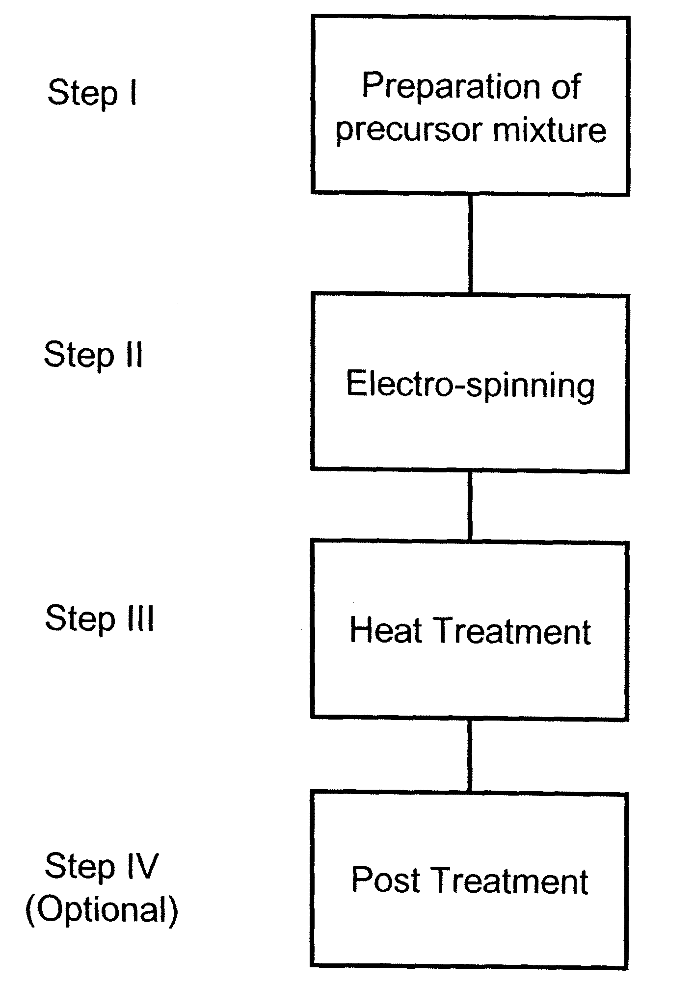
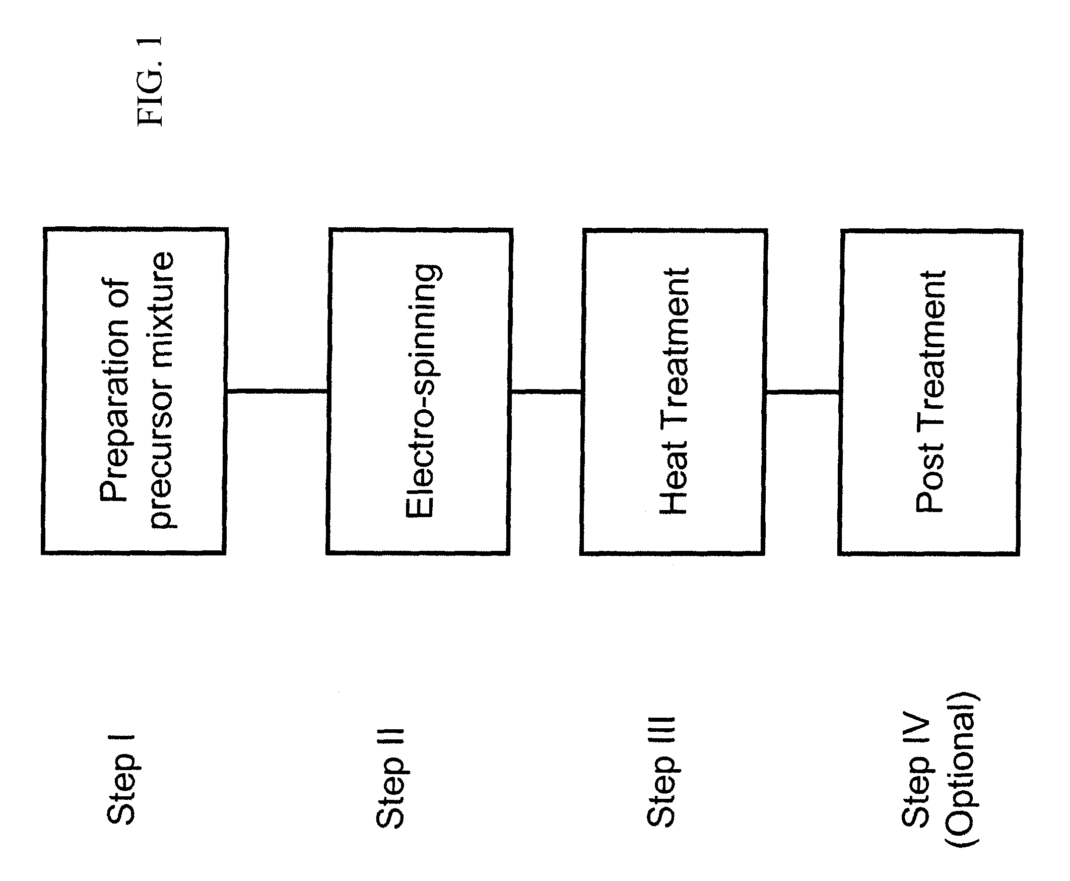
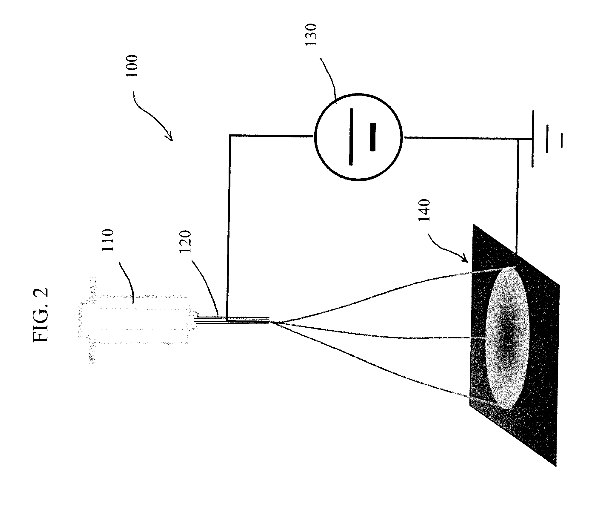
[0034]A precursor solution was prepared according to the following steps: A polymer mixture of PMMA and PAN in the weight ratio of 1.5:1 was first dissolved in the excess of DMF (×8 by weight) as the solvent to form solution 1. Separately, polymer PANI was dissolved in solvent DMF in the weight ratio of 1:20 to form solution 2; and 1,10-phenanthroline iron(II) perchlorate was dissolved into DMF in the weight ratio of 1:20 to form solution 3. The solutions 1, 2 and 3 were then mixed together in the volume ratio of 5:3:1 to form the final precursor solution. The precursor solution thus formed was electrospun to the polymeric nanofibers under an applied voltage of 1 kV / cm. A representative image of the polymeric nanofiber is shown in FIG. 3. The nanofibers thus prepared were subsequently transferred to a calcination dish and subjected to the heat-treatment. The heat treatment consisted of the following steps; the sample was heated in flowing air at 200° C. for 8 hours before the second...

example 2

[0035]The nanofibrous catalyst prepared according to Example 1 was made into the cathode of a fuel cell membrane electrode assembly (MEA). A catalyst ink was first prepared by mixing the catalyst powder from Example 1 with a Nafion ionomer solution so that the weight ratio of the catalyst to Nafion was 1:1. The ink was subsequently sprayed over a carbon paper (5 cm2, Avcarb), which was then heated under vacuum at 80° C. for 1 hour. The catalyst loading after drying was 1.8 mg cm−2. For the anode, an ink solution containing Pt / C (20 mg, 20 wt % of Pt, BASF), Nafione (5 wt % solution, Aldrich,), ethanol and water was sonicated for 1 hour and stirred for 0.5 hour, and then sprayed onto a carbon paper (5 cm2, Avcarb), which was then heated under vacuum at 80° C. for 1 hour. The Pt loading was 0.5 mg cm−2. The prepared cathode and anode were then pre-pressed against either side of a Nafion® 211 membrane (DuPont) at 120° C. for 1 minute using a load of 500 lb. The pre-pressed assembly was...

example 3

[0036]The MEA prepared according to Example 2 was installed in a fuel cell test station (Scribner 850e), and the cell performance was evaluated. The fuel cell test was carried out using a single cell with serpentine flow channels, and a geometric electrode surface area of 5 cm2. UHP grade gases were used. During the test, the cell temperature was kept at 80° C. Gases were humidified at 80° C. and were kept at a constant flow rate of 0.3 L min−1 for H2 and 0.4 L min−1 for O2, respectively. The total pressure was set at 22 psig for both anode and cathode. Shown in FIG. 4 is the polarization curve of cell voltage (E_stack) as a function of cell current density (I) and was obtained by scanning the cell current from 0 to maximum at a scan rate of 1 mA s−1. In the same chart, the power density, which is the product of the cell voltage and current density, was also plotted.


PUM

PropertyMeasurementUnit
temperatureaaaaaaaaaa
electric fieldaaaaaaaaaa
temperatureaaaaaaaaaa

Abstract

A nanofibrous catalyst and method of manufacture. A precursor solution of a transition metal based material is formed into a plurality of interconnected nanofibers by electro-spinning the precursor solution with the nanofibers converted to a catalytically active material by a heat treatment. Selected subsequent treatments can enhance catalytic activity.

Description

GOVERNMENT INTEREST[0001]The United States Government has certain rights in this invention pursuant to Contract No. DE-AC02-06CH11357 between the United States Department of Energy and Chicago Argonne, LLC as operator of Argonne National Laboratories.FIELD OF THE INVENTION[0002]The present invention relates generally to the field of catalysts. More particularly the invention relates to nanofibrous electrocatalysts and methods of manufacture. In addition, the invention relates to a fabric catalyst and method of preparation where the fibers have nanometer dimensions providing enhanced catalytic performance, particularly for proton exchange membrane fuel cell and lithium-air battery applications.BACKGROUND OF THE INVENTION[0003]The current invention discloses a method of preparing a fabric electrode catalyst with diameters of the fibers having nanometer dimensions. Such nanofiber catalysts can be used in proton exchange membrane fuel cell (PEMFC) and Li-air battery (LAB) applications.[...

Claims


Application Information

Patent Timeline
Patent Type & Authority Patents(United States)
IPC IPC(8): H01M4/90C01B31/02H01M12/08B82Y30/00B82Y40/00H01M8/10H01M50/437
CPCH01M4/9083C01B31/022C01B31/0246H01M4/9016H01M12/08B82Y30/00B82Y40/00H01M2008/1095Y02E60/50Y02E60/523C01B32/166Y02E60/10Y02P70/50H01M50/437C01B32/158H01M50/44H01M4/382H01M4/8828H01M4/9041H01M4/926H01M8/02H01M8/0263H01M8/1004H01M8/1018H01M8/1023H01M8/1039H01M10/0525H01M10/0568H01M10/0569H01M10/0585H01M2004/027H01M2004/8684H01M2004/8689H01M2300/0028
Inventor LIU, DI JIASHUI, JIANGLANCHEN, CHEN
Owner UCHICAGO ARGONNE LLC
Learn More