
Adhesive body comprising conductive polymer-metal complex and substrate and method for forming the same, conductive polymer-metal complex dispersion liquid, method for manufacturing the same and method for applying the same, and method for filling hole using conductive material

a technology of conductive polymer metal and conductive polymer, which is applied in the direction of film/foil adhesives, printed element electric connection formation, and semiconductor/solid-state device details. it can solve the problems of increasing packaging area and elongation of signal transmission paths, and material obtained by this method also failed to achieve a sufficiently high conductivity. , to achieve the effect of fine conductive pattern, high stability and satisfactory storability

Active Publication Date: 2017-04-11
NAT INST FOR MATERIALS SCI
View PDF12 Cites 0 Cited by
  • Summary
  • Abstract
  • Description
  • Claims
  • Application Information

AI Technical Summary

Benefits of technology

The conductive polymer-metal complex dispersion liquid described in this patent is stable and can be easily applied to various substrates, including materials that are not very sticky. Additionally, it can be used with existing techniques and instruments for applying a thin layer accurately. An adhesive body made from this dispersion liquid and a substrate can strongly adhere to various surfaces, including PTFE which is not very adhesive. Furthermore, it can be easily filled into narrow holes.

Problems solved by technology

Accordingly, the wire bonding method requires to secure a region for the wire bonding in the circumference of the LSI chip, which leads to a problem involving an increase in the packaging area as well as an elongation of the signal transmission path.
In addition, the number of the signal paths between LSI chips is limited by the number of the bonding terminals capable of being provided around the LSI chips.
Nevertheless, the material obtained by this method also failed to achieve a sufficiently high conductivity which should be possessed by a filling material for the TSV, and a problematically high manufacturing cost is still associated because a relatively non-noble metal such as a copper cannot be used.
Moreover, if a conductive polymer-metal complex having a satisfactory conductivity is given, and also if it has not only a property similar to that of an existing conductive body such as a metal but also an ability of adhering such a complex strongly by a simple operation onto various substrates usually posing a difficulty in adhering a conductive body such as PTFE (polytetrafluoroethylene), its applicability may dramatically be widened.
On the other hand, a hole having a high aspect ratio such as a via having a small diameter, when being filled with a conductive substance such as a metal, requires a complicated processing such as a procedure for ensuring the first entrance of a processing fluid into the hole, such as a transient reduction in pressure.
In such a form, it is difficult to form the seed layer uniformly inside of the via and the number of fabricating processes increases problematically for achieving the inside of the via which is close to a complete cylinder.

Method used


Image

  • Adhesive body comprising conductive polymer-metal complex and substrate and method for forming the same, conductive polymer-metal complex dispersion liquid, method for manufacturing the same and method for applying the same, and method for filling hole using conductive material
  • Adhesive body comprising conductive polymer-metal complex and substrate and method for forming the same, conductive polymer-metal complex dispersion liquid, method for manufacturing the same and method for applying the same, and method for filling hole using conductive material
  • Adhesive body comprising conductive polymer-metal complex and substrate and method for forming the same, conductive polymer-metal complex dispersion liquid, method for manufacturing the same and method for applying the same, and method for filling hole using conductive material

Examples


reference example 1

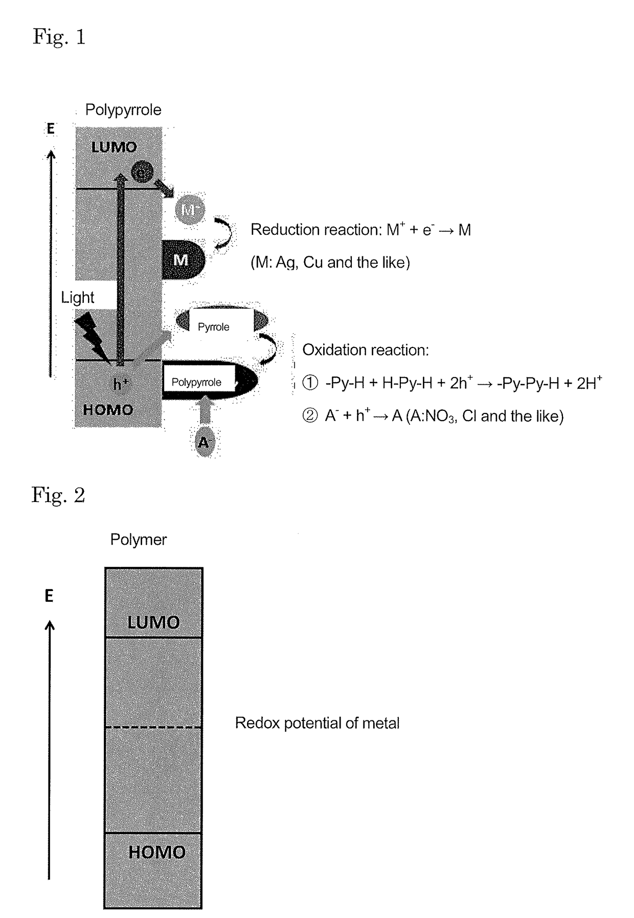
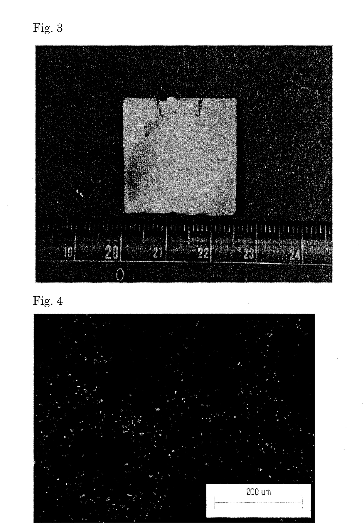
[0112]Using pyrrole, 3,4-ethylenedioxythiophene (EDOT) and aniline as monomers for obtaining a conductive polymer, Cu2+ and Ag+ as metal ions and chloride ion (Cl−) for Cu2+ and nitrate ion (NO3−) for Ag+ as anions, ultraviolet light irradiation was performed to precipitate a conductive polymer-metal complex. With varying types and concentrations of the monomers and varying types and concentration of the metal ions, 30 types of experiments were performed. It should be understood that these are merely examples and are not intended to restrict the technical scope of the present invention which is defined in Claims. These experiments were performed using the following experimental conditions and measurement conditions.[0113]Typical experimental condition[0114]Temperature: Room temperature[0115]Solvent: Acetonitrile, ethanol and water[0116]Substrate: Glass[0117]Ultraviolet light intensity: 50 mW / cm2 [0118]Wavelength: 436 nm, 405 nm, 365 nm (bright line)[0119]Precipitation time: 0.5 to 2...

reference example 2

[0128]The conductive polymer-metal complex used in the present invention and Non Patent Literature 4 were compared in an experiment. The following experimental conditions and measurement conditions were employed.[0129]Pyrrole concentration: 0.1 mol / L[0130]Metal ion concentration: 0.1 mol / L[0131]Anion: NO3−, Anion concentration: 0.1 mol / L[0132]Solvent: Acetonitrile[0133]Substrate: Glass[0134]Reaction time: 60 min

[0135]As a result, when using the pyrrole as a monomer and Ag+ as a metal ion, the resistance of the precipitate obtained precipitation performed for about 1 hour in the method of Non Patent Literature 4 was as substantially high as 105 to 107Ω. When using Cu2+ instead of Ag+, no precipitation of the conductive polymer-metal complex was observed.

[0136]On the other hand, when processing the combination of the pyrrole and Ag+ based on the manufacturing method of the conductive polymer-metal complex used in the present invention, the precipitation for a time period less than 20 ...

reference example 3

[0153]An example of the behavior of a reaction system in which both of a light and a heat are employed as energies upon precipitating the conductive polymer-metal complex is shown below.

[0154]The substrate employed was a silica glass (8×8×0.9 mm), and this substrate was immersed in an acetonitrile solution containing silver nitrate (1.0 mol-dm−3) serving as sources of a metal cation and a doping anion and pyrrole (0.5 mol-dm−3) as an organic monomer. The reaction system was subjected to light irradiation using an ultra high pressure mercury lamp (bright line wavelength: 436 nm, 405 nm, 365 nm) with the intensity being set at 30 mW·cm−2 or 60 mW-cm−2. The reaction system was heated using a hot plate and the temperature was set at 50° C. or 70° C. The temperature of the reaction system when not heated was 30° C.

[0155]When the light irradiation was not performed and the heating temperature was changed, the solution remained transparent at 30° C. and 50° C. regardless of the time elapse...


PUM

PropertyMeasurementUnit
diameteraaaaaaaaaa
diameteraaaaaaaaaa
sizeaaaaaaaaaa

Abstract

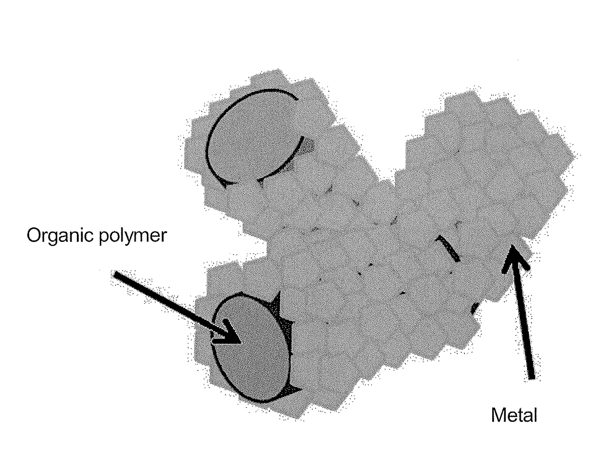
A conductive polymer-metal complex becomes to be adhered simply and strongly on the surface of a substrate such as PTFE. By subjecting a solution containing a monomer which provides a conductive polymer, an anion, and a metal ions such as Ag+, Cu2+, Cu+ and the like to an irradiation with light having an energy required for exciting an electron to an energy level capable of reducing the metal ion, such as ultraviolet light, under an appropriated condition, thereby precipitating the conductive polymer-metal complex as being dispersed in the reaction liquid. By supplying this dispersion liquid onto various substrates, the complex microparticles in the dispersion liquid enter into and mate with the narrow holes on the surface of the substrate. As a result, the complex precipitate formed on the surface of the substrate and the substrate can be adhered strongly to each other.

Description

TECHNICAL FIELD[0001]The present invention relates to an adhesive body comprising a conductive polymer-metal complex and a substrate resulting from a simultaneous precipitation of a conductive polymer and a metal and a method for forming the adhesive body. More specifically, it relates to an adhesive body utilizing that, when a dispersion liquid of a conductive polymer-metal complex is supplied to a substrate such as a polymer, by allowing the microparticles of the conductive polymer-metal complex to enter into a narrow hole existing on this substrate's surface, the conductive polymer-metal complex formed on the substrate adheres to the substrate strongly, as well as a method for forming the same.[0002]The present invention also relates to a dispersion liquid of the conductive polymer-metal complex resulting from a simultaneous precipitation of a conductive polymer and a metal and a method for manufacturing the same. The present invention also relates to a method for applying the di...

Claims


Application Information

Patent Timeline
Patent Type & Authority Patents(United States)
IPC IPC(8): C09D17/00H01L21/768H05K1/09C09D201/00H01B1/22C09J7/02C08G73/02C09J165/00C08L79/02C08K3/08C08L65/00H05K3/40H01L23/498C09J7/20
CPCH05K1/095C08G73/0266C09D17/00C09D201/00C09J7/02H01B1/22H01L21/76898C08G2261/3221C08G2261/3223C08G2261/43C08G2261/964C08K3/08C08L65/00C08L79/02C09J165/00C09J2205/102C09J2465/00H01L23/49883H05K1/097H05K3/4069H05K2201/032Y10T428/24339C09J7/20C09J2301/408
Inventor KAWAKITA, JINCHIKYO, TOYOHIROHASHIMOTO, YASUOHORVATH, BARBARA
Owner NAT INST FOR MATERIALS SCI
Learn More