Pressurized internal circulating fluidized-bed boiler

Inactive Publication Date: 2001-07-31
EBARA CORP
View PDF8 Cites 21 Cited by
  • Summary
  • Abstract
  • Description
  • Claims
  • Application Information

AI Technical Summary

Benefits of technology

The pressurized bubbling type fluidized-bed electric generating system is controlled to meet a load imposed thereon by varying the height of the fluidized bed in the combustor. More specifically, the fluidized medium is drawn from the combustor into the storage container to change heat transfer area of the heat transfer tube, thereby controlling the steam generation to meet the load. When the heat transfer surfaces of the heat transfer tube are exposed to the gas, the heat transfer coefficient thereof is lowered, and hence the amount of heat recovered is lowered. Since the exhaust gas emitted from the fluidized bed is cooled by the exposed heat transfer surfaces, the temperature of the exhaust gas supplied to the gas turbine is lowered, thus reducing the output energy of the gas turbine.
However, the above control process is disadvantageous in that the bed material storage container is necessary to withdraw and return the high-temperature fluidized medium from and into the combustor, it is not easy to withdraw and return the fluidized medium at high temperature and pressure, and agglomeration tends to occur when the fluidized medium of high heat capacity are taken into and out of the bed material storage container.
Furthermore, since the pressurized fluidized-bed boiler is under pressure, the heat transfer tube in a splash zone of the fluidized bed is more subject to erode than that in the atmospheric fluidized-bed boilers (AFBC). Another problem is that an large amount of carbon monoxide is produced because an exhaust gas emitted from the fluidized bed is cooled by the heat transfer tube and the exhaust gas remains in the fluidized bed for a short period of time as the height of the fluidized bed is reduced in the time of low load.
conventionally, the pressurized bubbling type fluidizedbed boiler comprises square combustors 146 accommodated in a circular pressure vessel 145 in a plan view as shown in FIG. 14. Therefore, a useless space is defined between the combustors 146 and the pressure vessel 145, resulting in a large-sized pressure vessel and increasing the construction cost of the boiler.
It is therefore an object of the present invention to provide a pressurized internal circulating fluidized-bed boiler for a combined-cycle electric generating system, which can be controlled to meet a load without varying the height of a fluidized bed, prevents agglomeration, minimize the emission of carbon monoxide and nitrogen oxide, and can increase a limestone utilization ratio

Problems solved by technology

It is conjectured that coal will have to be relied upon as a major energy resource because greater dependency on nuclear and oil energies is not favorable at present.
To meet such a demand, atmospheric fluidized-bed boilers (AFBC) capable of burning coals of different kinds for electric generation have been developed because a stable energy supply cannot be achieved by pulverized coal boilers which pose a limitation on available coal types.
However, the atmospheric fluidized-bed boilers (AFBC) fail to perform the functions that have been expected.
In addition, since only steam turbines can be combined with the atmospheric fluidized-bed boilers, there are certain limitations on attempts to increase the efficiency and energy output of the atmospheric fluidized-bed boilers.
(A) Disadvantage in load control
Since the exhaust gas emitted from the fluidized bed is cooled by the exposed heat transfer surfaces, the temperature of the exhaust gas supplied to the gas turbine is lowered, thus reducing the output energy of the gas turbine.
However, the above control process is disadvantageous in that the bed material storage container is necessary to withdraw and return the high-temperature fluidized medium from and into the combustor, it is not easy to withdraw and return the fluidized medium at high temperature and pressure, and agglomeration tends to occur when the fluidized medium of high heat capacity are taken into and out of the bed material storage container.
Furthermore, since the pressurized fluidized-bed boiler is under pressure, the heat transfer tube in a splash zone of the fluidized bed is more subject to erode than that in the atmospheric fluidized-bed boilers (AFBC).
Another problem is that an large amount of carbon monoxide is produced because an exhaust gas emitted from the fluidized bed is cooled by the heat transfer tube and the exhaust gas remains in the fluidized bed for a short period of time as the height of the fluidized bed is redu

Method used


Image

  • Pressurized internal circulating fluidized-bed boiler
  • Pressurized internal circulating fluidized-bed boiler
  • Pressurized internal circulating fluidized-bed boiler

Examples


first embodiment

(First embodiment)

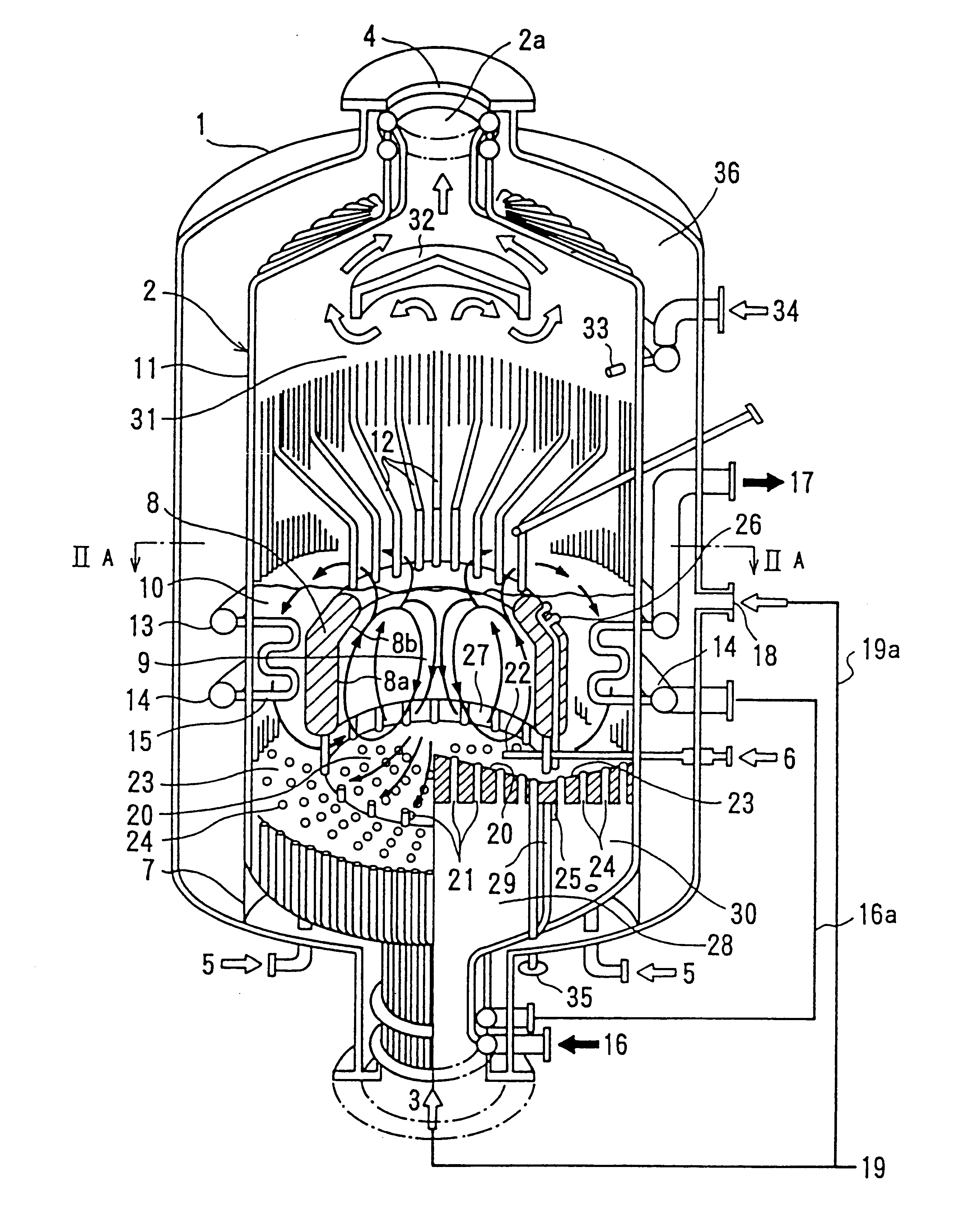
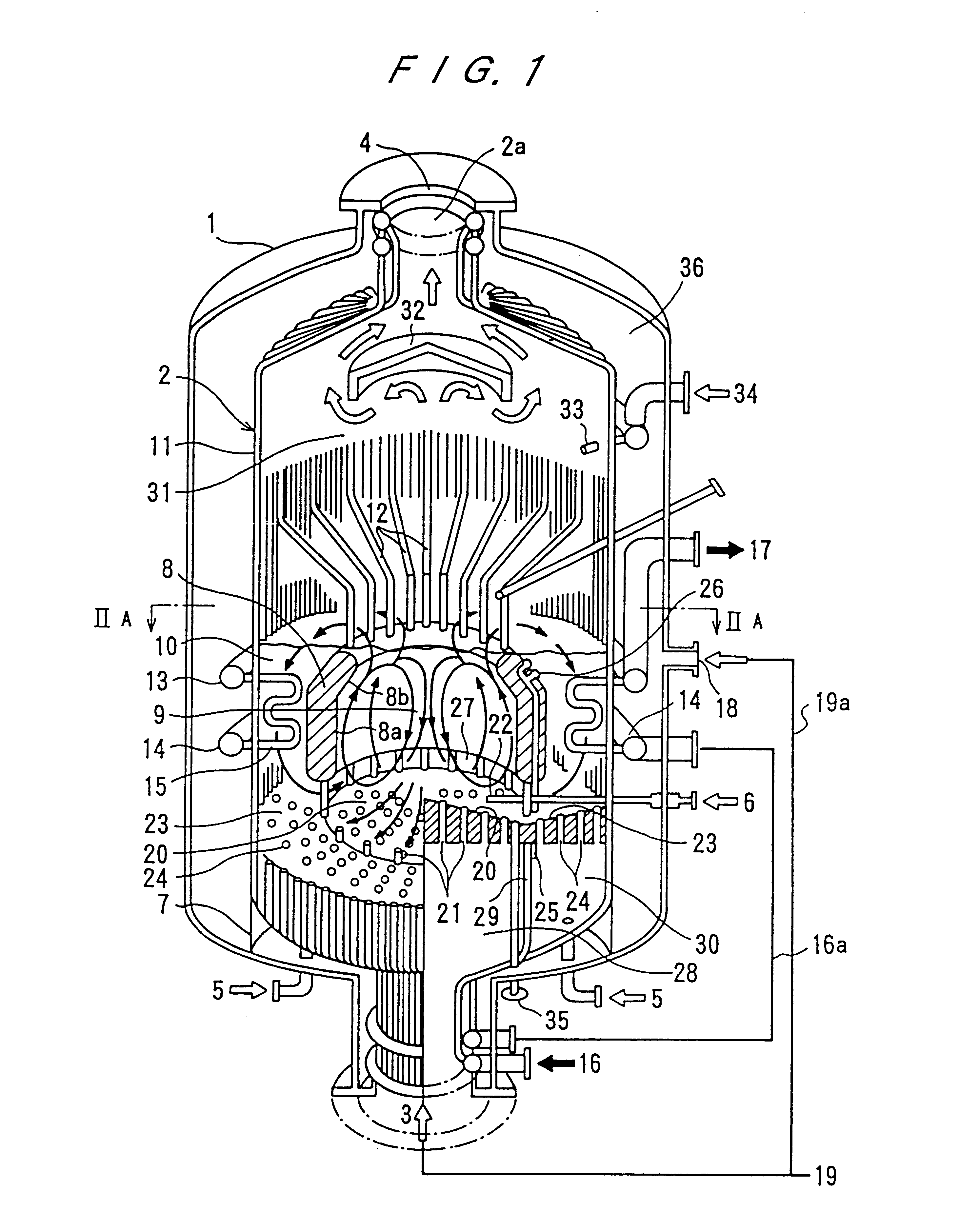
As shown in FIG. 1, the combined-cycle electric generating system includes a pressure vessel 1 which is of a cylindrical receptacle-like structure. The pressure vessel 1 is provided with a combustion gas outlet 4 at the top, a fluidizing air inlet 3 and thermal energy recovery chamber control air inlets 5 at the bottom. The pressure vessel 1 is constructed in such a way that it can retain higher inner pressure than atmospheric pressure. The pressure vessel 1 may be of a spherical body.

Inside the pressure vessel 1, there is provided a cylindrical combustor 2 which is an air tight vessel having a cylindrical membrane wall 11 consisting of water tubes. A main fluidized bed combustion chamber 9 is formed inside the cylindrical combustor 2. On the top of the cylindrical combustor 2, there is provided a combustion gas outlet 2a which is connected to the combustion gas outlet 4 of the pressure vessel 1. The cylindrical combustor 2 is firmly held to the bottom by a cylindr...

second embodiment

(Second embodiment)

FIG. 6 shows a system diagram of a combined-cycle electric generating system which incorporates a pressurized internal circulating fluidized-bed boiler according to a second embodiment of the present invention.

As shown in FIG. 6, an exhaust gas discharged from a pressure vessel 1 is introduced through an exhaust gas flow path 50 into a cyclone 51. Flying ashes collected by the cyclone 51 fall by gravity and are stored in a seal mechanism 52, from which they are carried by ash recycling 53 and returned to a thermal energy recovery chamber 10 through a recycled ash inlet pipe 54 that extends through side walls of a pressure vessel 1 and a cylindrical combustor 2.

Since flying ashes are recycled into the thermal energy recovery chamber 10, the average diameter and specific gravity of particles in the thermal energy recovery chamber 10 are reduced. While the average diameter of particles in the main combustion chamber 9 is about 0.6 mm, the diameter of particles which ...

third embodiment

(Third embodiment)

FIG. 7 illustrates a pressurized internal circulating fluidized-bed boiler according to a third embodiment of the present invention, the boiler including a system for processing an exhaust gas.

As shown in FIG. 7, flying ashes collected by a cyclone 51 in an exhaust gas flow path 50 are cooled by an ash cooler 77. A coolant used in the ash cooler 77 may be water supplied to the boiler or fluidizing air for effective recovery of the thermal energy from the ashes.

The cooled ashes are introduced through a lock hopper 78 into a classifying tank 79 in which they are mixed with flying ashes supplied from a dust collector 55 through an ash cooler 56 and a lock hopper 57, and the mixture is classified. In the illustrated embodiment, classifying air 80 is charged into the classifying tank 79 through an air diffuser pipe 81 for fluidized bed classification. However, this embodiment may not necessarily be limited to such type of classification.

Particles of unreacted desulfuriz...


PUM


Abstract

A pressurized internal circulating fluidized-bed boiler is incorporated in a combined-cycle electric generating system in which a fuel such as coal, petro coke or the like is combusted in a pressurized fluidized bed and an exhaust gas produced by the combusted fuel is introduced into a gas turbine. The pressurized internal circulating fluidized-bed boiler includes a pressure vessel, a combustor disposed in the pressure vessel and a main fluidized bed combustion chamber provided with an air diffusion device. A thermal energy recovery chamber is partitioned from the main combustion chamber by an inclined partition wall. A fluidized medium flows into and out of the main combustion chamber and the thermal energy recovery chamber. A free board is provided integrally above the main combustion chamber and the thermal energy recovery chamber so that combustion gas from the main combustion chamber and the thermal energy recovery chamber is mixed in the free board.

Description

BACKGROUND OF THE INVENTION1. Field of the InventionThe present invention relates to a pressurized internal circulating fluidized-bed boiler, and more particularly to a pressurized internal circulating fluidized-bed boiler for use in a pressurized fluidized-bed combined-cycle electric generating system in which a fuel such as coal, petro coke, or the like is combusted in a pressurized fluidized bed and an exhaust gas produced by the combusted fuel is introduced into a gas turbine.2. Description of the Prior ArtEfforts to reduce the emission of carbon dioxide from various sources are important in view of environmental damages that are being caused by air pollution which appears to be more and more serious on the earth. It is conjectured that coal will have to be relied upon as a major energy resource because greater dependency on nuclear and oil energies is not favorable at present. To suppress carbon dioxide emission and provide a substitute for oil and nuclear power, there has been...

Claims


Application Information

Patent Timeline
IPC IPC(8): C10J3/46C10J3/76C10J3/00F01K23/06F23C10/06F23C10/28F23C10/20F23C10/16F23C10/00F22B31/00F23C10/10F23L9/00F23L9/04F23L7/00F23C10/08C10J3/56C10J3/86F02C3/28F22B3/08
CPCC10J3/463C10J3/56C10J3/723C10J3/76C10J3/86C10J2200/09C10J2200/15C10J2300/0956C10J2300/1675C10J2300/1687F01K23/062F01K23/067F22B31/0092F23C10/06F23C10/10F23C10/16F23C10/20F23C10/28F23L7/00F23L9/04F23L2900/07005F23L2900/07009Y02E20/16Y02E20/18Y02E20/34Y02P20/10Y02P20/129F22B31/0015F22B31/0069
Inventor NAGATO, SHUICHIHORIO, MASAYUKIOSHITA, TAKAHIROMIYOSHI, NORIHISATOYODA, SEIICHIROSHIMOKURA, AKIRASHINANO, TOMOYUKIHOSODA, SHUGO
Owner EBARA CORP
Why Eureka
Try Eureka