[0003] (1) Due to the large power generation capacity of large generators, the components such as stator and rotor windings, main shaft bearings, and excitation systems generate a lot of heat during operation. Once reliable and effective cooling is lacking, it is easy to affect the quality of power generation due to burning , and even cause
downtime accidents, so effective cooling is one of the main auxiliary functions of generators
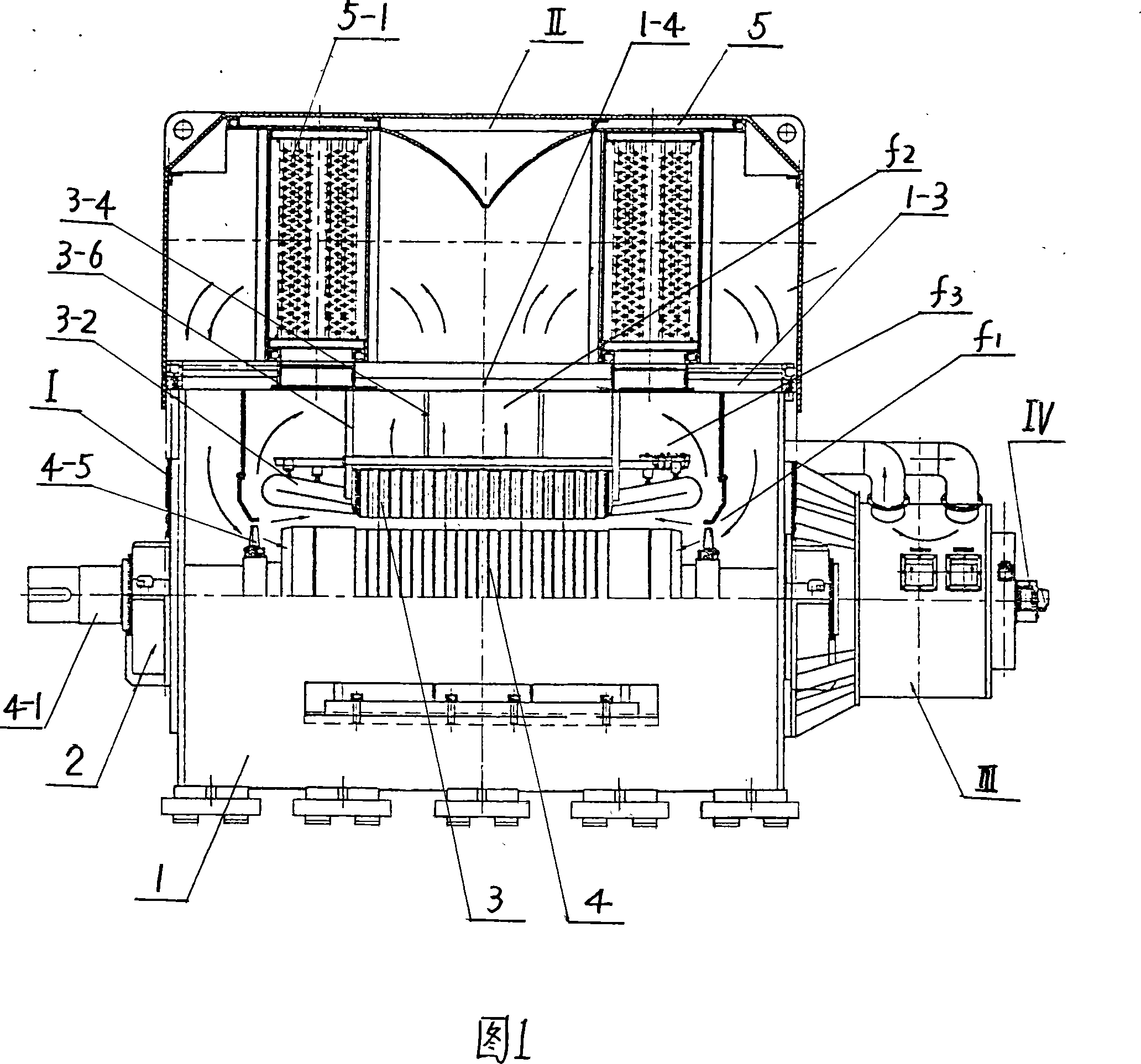
In the existing technology, the cooler is usually installed at the bottom of the main generator. When the generator set is installed, a huge installation room must be built below the ground to accommodate the cooler and the installation and maintenance
work space. Not only is the installation project complicated , heavy
workload, long
cycle time, high
material consumptionAnd it brings a lot of trouble to the maintenance of the installation, debugging and use process.
Secondly, due to the long distance between the installation position of the cooler and the stator and rotor of the main cooling part, the
cold air transmission distance is long, the pressure and
energy loss are high, and the
cooling effect is affected
Moreover, there is usually only one
heat exchanger in the cooler. Once a failure occurs, it will take a long time to stop for maintenance, which will affect production efficiency; Poor insulation will easily lead to
insulation failure and poor operation reliability, especially at the end of the coil, where
heat energy is concentrated and covered by a
guard ring, which is the most prone to failure; Fourth, exposed
air cooling is generally used for the
exciter, and the
cold air can only be blown to other parts. The surface does not have the effect of heat dissipation inside the
exciter, and at the same time, oil and dust are easy to enter the inside of the body, resulting in
insulation failure,
short circuit and other accidents
Although the cooling system of the generator has been continuously improved in the prior art, the
cooling effect is still not ideal. For example, some axial ventilation slots are set at the bottom of the rotor coil, but since the cooling air enters the slot from both ends, it cannot circulate. Difficult to achieve ideal
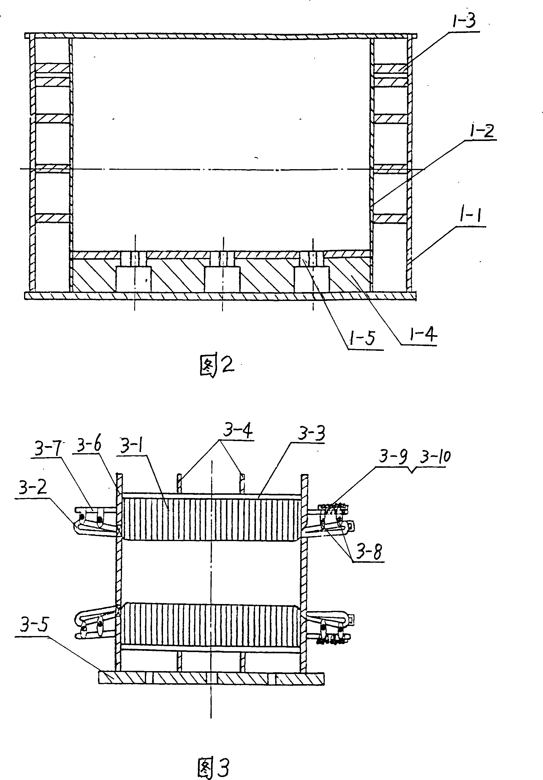
cooling effect[0004] (2) The base of the generator mostly adopts the integral structure of the stator core and the base, and the adjustment of the air gap is very difficult, which is mainly guaranteed by the
machining accuracy of the components, resulting in difficult
processing and
assembly, and affects the performance of the whole
machineDue to the poor rigidity of this structure, the generator vibrates too much and is prone to heat, which cannot ensure the balance of the air gap during the operation of the generator, and generates vibration
harmonic voltage, which has a negative
impact on the
power grid.
In addition, separate bearing housings and rolling bearings are generally used in the frame structure, which occupy a large axial space for installation and poor sealing, which also affects the rigidity of the stator shaft.
[0005] (3) The stator of the generator usually adopts an
internal pressure structure in which the stator and the
machine base are integrally connected. Since the stator core is integrated with the
machine base, the machine base must be processed first before the stator
punching lamination, coil off-line, etc. , unable to work in parallel, resulting in a long
production cycle, low efficiency, and cumbersome
assembly operations, time-consuming and labor-intensive
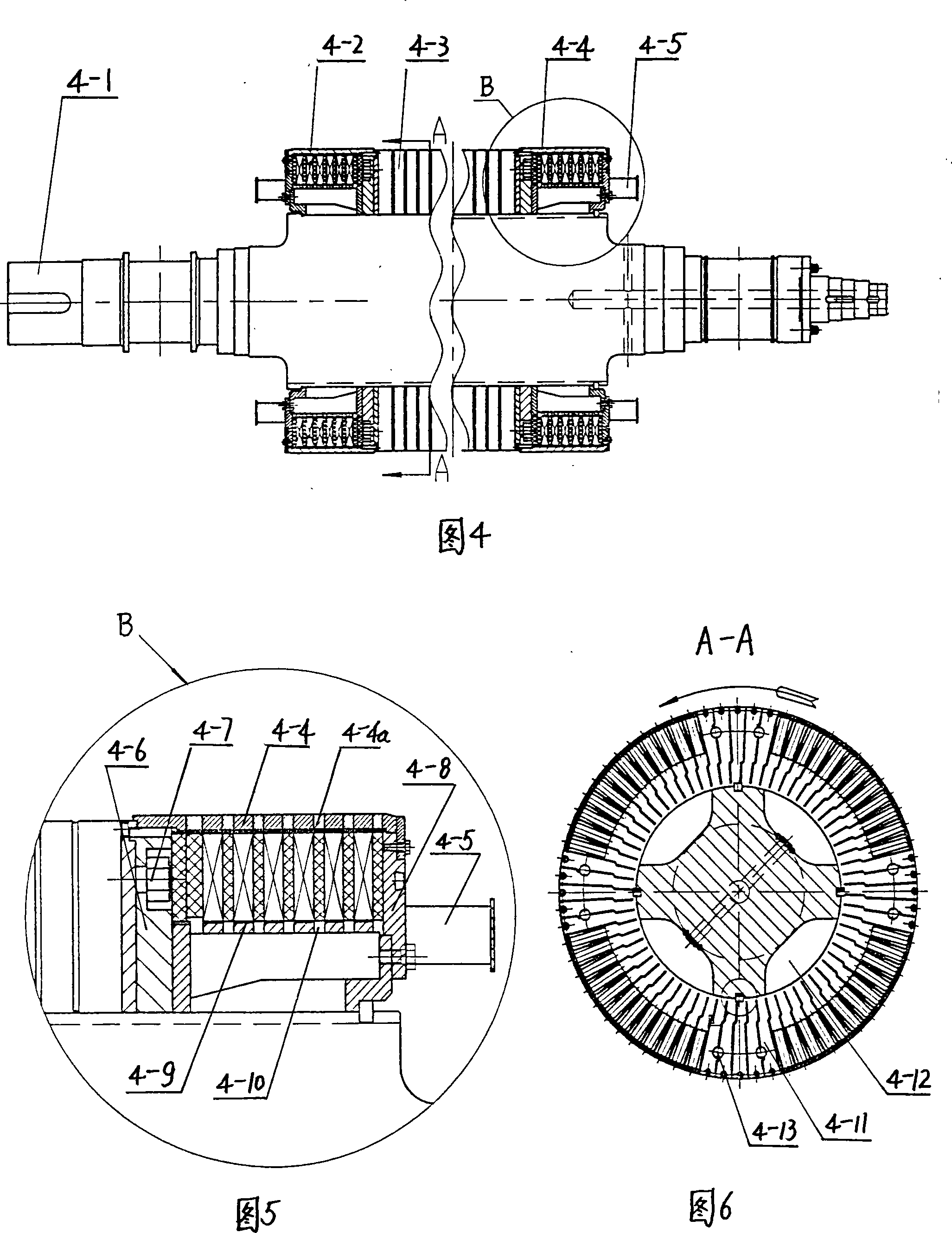
Due to the slender structure of the rotor shaft, the production and
processing cycle is long, the process is many, the cost is high, the manufacturing process is complicated, and the material
utilization rate is low
In order to improve the heat dissipation performance of the rotor, some heat dissipation grooves are set at the bottom of the wire slot under the rotor shaft. However, due to the lack of radial ventilation circulation, the internal heat dissipation is still only transmitted to the rotor surface by conduction, and the heat dissipation performance is not ideal. Require
Secondly, the rotor in the prior art usually adopts a single damping circuit, which has poor anti-interference ability. When the excitation is powered by an external line network, interference is prone to occur due to large fluctuations in voltage and
capacitance.
Especially when there is a paroxysmal abnormal operation state, the generator cannot quickly restore the stability of the system, which affects the production power supply quality of the machine
[0007] (5) The current brushless excitation system usually uses a generator with a low number of poles, and the number of
magnetic poles is only 4 poles, 6 poles or 8 poles
Therefore, the generated
excitation current frequency is low and the voltage pole change rate is high, resulting in poor power generation quality of the main generator
Secondly, the rectification mechanism generally adopts a double-sided installation structure composed of a positive plate, a negative plate and an intermediate insulating partition, the rectification effect is poor, and the structure is not compact
In addition, most of the existing excitation systems lack effective cooling measures, often due to the influence of temperature rise, the stability is not good, the normal operation of the excitation system cannot be guaranteed, and even failures occur
[0008] (6) The collector ring in the generator rotor shaft current grounding detection device is usually installed between the generator bearing and the end cover, and a radial lead hole is set on the shaft. The collector ring has a large volume and the
peripheral surface linear velocity If it is too high, the brushes will
wear out quickly, requiring frequent maintenance and replacement of brushes
For frequent maintenance and overhaul, the protective cover is often discarded, so that the collector ring is exposed outside, resulting in accelerated wear of the components, especially when the generator is installed outdoors, rainwater, oil, and dust are easy to enter the radial wiring holes, resulting in Lead wire damage,
short circuit and other faults, even lead to accidents
In addition, the collector ring body is bulky, labor-intensive and material-intensive to manufacture, takes up a lot of space, and is inconvenient to maintain and overhaul

