
Miniature solid or hollow silicon needle, silicon needle array and preparing method thereof

A silicon needle and hollow technology, which is applied in the fields of microneedle, manufacturing of microstructure devices, semiconductor/solid-state device manufacturing, etc., can solve the problems of high manufacturing cost of micro hollow silicon needle, high startup and maintenance costs, and high price. The effect of low cost, simple manufacturing process and low cost

Inactive Publication Date: 2010-09-01
TSINGHUA UNIV
View PDF0 Cites 7 Cited by
  • Summary
  • Abstract
  • Description
  • Claims
  • Application Information

AI Technical Summary

Problems solved by technology

[0013] In the above-mentioned literature, although the shapes of micro-silicon needles are different, there is no silicon needle structure similar to traditional hypodermic needles; the material for making micro-silicon needles is single crystal silicon wafer or (100) plane For crystalline silicon wafers, the manufacturing method usually adopts the process of combining isotropic etching of silicon or anisotropic etching (including wet etching and / or dry etching), and the through holes of micro hollow silicon needles are all made by DRIE. (Deep Reactive Ion Dry Etching) equipment for monolithic processing; because DRIE equipment is expensive, start-up and maintenance costs are high, and it belongs to monolithic processing, and it is difficult to prepare through holes on monocrystalline silicon wafers with a thickness of hundreds of microns. It is very time-consuming, so the production cost of micro hollow silicon needles remains high

Method used


Image

  • Miniature solid or hollow silicon needle, silicon needle array and preparing method thereof
  • Miniature solid or hollow silicon needle, silicon needle array and preparing method thereof
  • Miniature solid or hollow silicon needle, silicon needle array and preparing method thereof

Examples


Embodiment Construction

[0042] The invention proposes a miniature solid or hollow silicon needle array and a manufacturing method thereof. The present invention is described below in conjunction with accompanying drawing, the structure of described miniature solid or hollow silicon needle array is as follows:

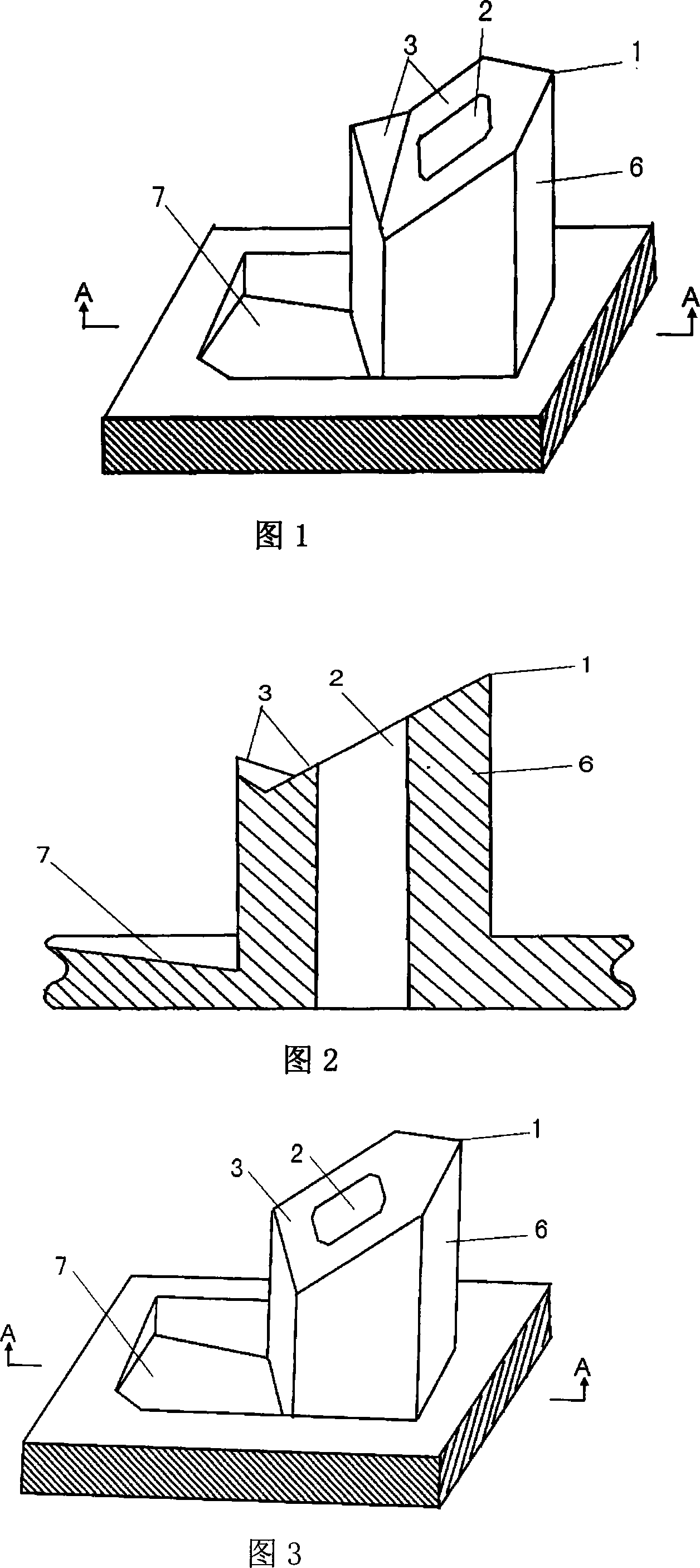
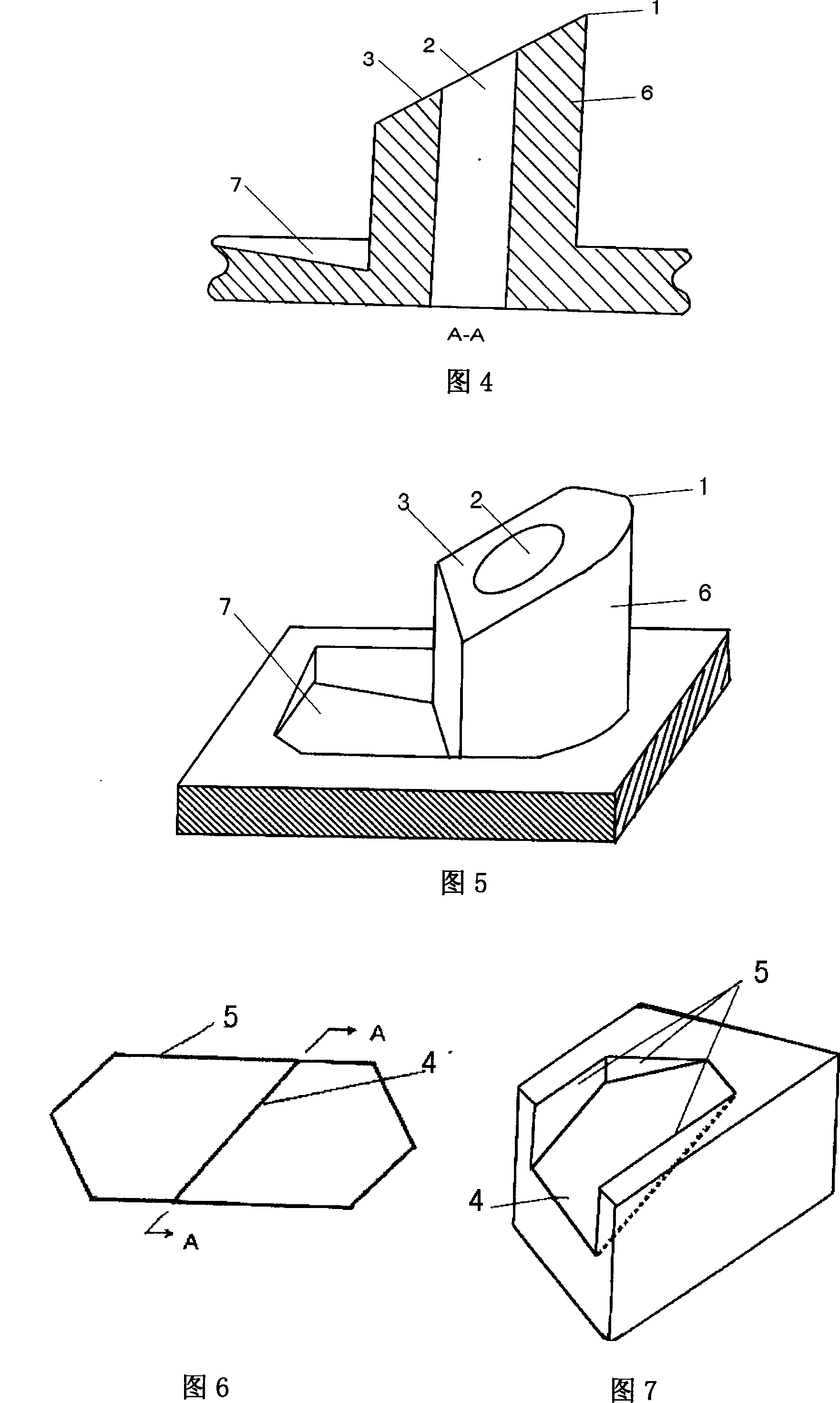
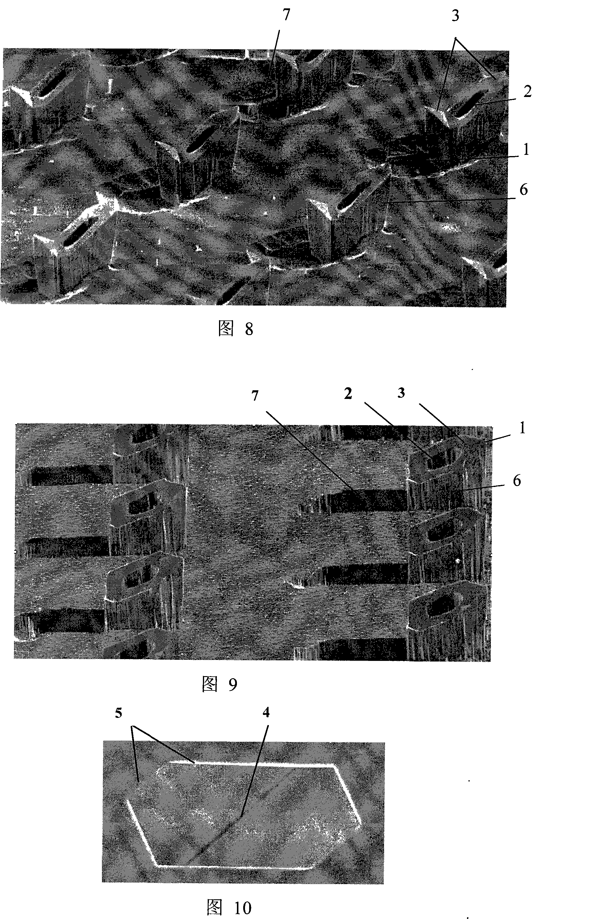
[0043] 1) The shape of the micro-silicon needle is similar to that of a traditional hypodermic needle. The lower end of the needle is a columnar body 6. There is at least one smooth slope 3 at the part where the needle tip is formed at the upper end of the needle. ) planes 5 are parallel; the bevel 3 is arc-shaped at the needle tip or has one or more sharp corners to form the apex 1 of the needle (as shown in Figures 1, 5, 8, and 9);

[0044] 2) There are polygonal, elliptical or circular holes 2 on the smooth slope 3 at the top of the needle tip, and these holes 2 and the bottom of the silicon needle are formed by six (111) surfaces 5 (as shown in Figures 6 and 10) The inverted triangular gr...


PUM

PropertyMeasurementUnit
thicknessaaaaaaaaaa
thicknessaaaaaaaaaa

Abstract

The invention discloses a miniature solid or hollow silicon needle, a silicon needle array and the manufacture method, belonging to the medical service and hairdressing apparatus and micro machining technical field. The lower end of the miniature silicon needle head is column. The upper needle point of the needle head is provided with at least one arc sharp corner to form the peak. A through holeis arranged on the peak and is connected with the inverse triangle groove at the bottom. By micro-electronics craft, at the positive and the back surfaces of the (110) crystal orientation monocrystalline silicon wafer, two kinds of inverse triangle grooves are processed in batches which are formed by six silicon (111) surfaces, using the anisotropism self-stop wet corrosion. Then the silicon needle and a through hole are manufactured by the DRIE method. The through hole is connected with the back inverse triangle groove. The invention has the advantages that: the solid or hollow silicon needle array can be manufactured in batches with low cost, high productivity and firm structure; the invention has a wider potential application in the transdermal drug delivery, micro body fluid extraction and other biomedical field.

Description

technical field [0001] The invention belongs to the technical fields of medical treatment, beauty equipment and micro-processing, and in particular relates to micro solid or hollow silicon needles, silicon needle arrays and a manufacturing method thereof. technical background [0002] Human skin has three layers of tissue: stratum corneum, active epidermis and dermis. The thickness of the outermost stratum corneum is about 10-50 microns, which is composed of dense corneocytes; below the stratum corneum is the epidermis, which is about 50-100 microns in thickness, contains active cells and a small amount of nerve tissue, but has no blood vessels . Below the epidermis is the dermis, which is the main component of the skin and contains a large number of living cells, nerve tissue, and blood vessel tissue. Since the outer diameter of the injection needle used in the traditional hypodermic injection method is generally 0.4 to 3.4 mm, the injection needle needs to penetrate the ...

Claims


Application Information

Patent Timeline
Patent Type & Authority Patents(China)
IPC IPC(8): A61M5/158A61M5/32A61M25/00B81C1/00H01L21/00A61M23/00A61M37/00
CPCA61M37/0015A61M2037/003A61B5/14514A61M2037/0053A61B5/1411A61B5/150022A61B5/150282A61B5/150984
Inventor 岳瑞峰王燕刘理天
Owner TSINGHUA UNIV
Learn More