Fuel cell using conductive polymer modified carbon based cobaltous hydroxide composite catalyst

A conductive polymer, composite catalyst technology, applied in organic compound/hydride/coordination complex catalysts, solid electrolyte fuel cells, physical/chemical process catalysts, etc., can solve the problems of less research, poor catalyst performance, etc. Low cost and favorable effect

Inactive Publication Date: 2009-10-07
ZHEJIANG UNIV
View PDF0 Cites 17 Cited by
  • Summary
  • Abstract
  • Description
  • Claims
  • Application Information

AI Technical Summary

Problems solved by technology

The research on non-noble metal catalysts mainly focuses on transition metal oxides, transition metal macrocyclic compounds and transition metals, among which MnO 2 Although Ag has better catalytic activity, it still has a certain gap compared with platinum (Liu et al., Journal o

Method used


Image

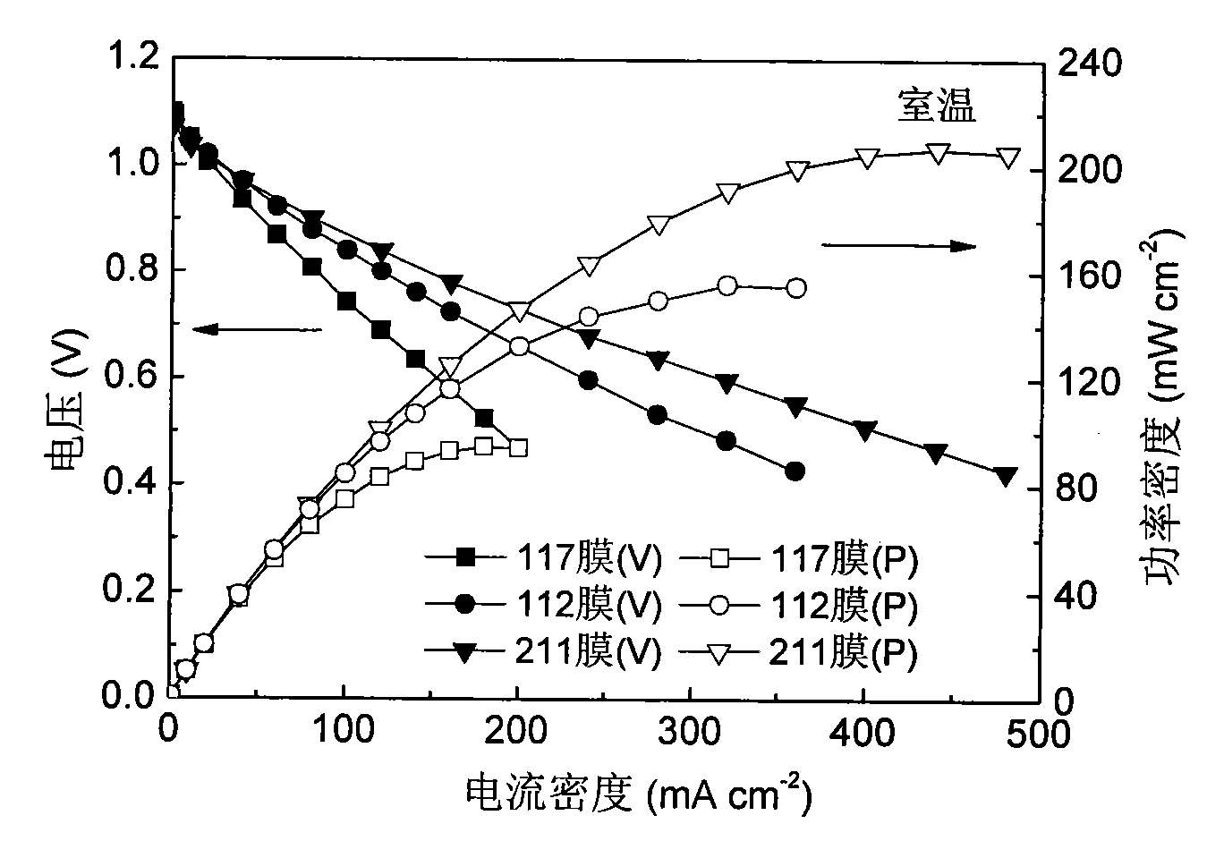
  • Fuel cell using conductive polymer modified carbon based cobaltous hydroxide composite catalyst
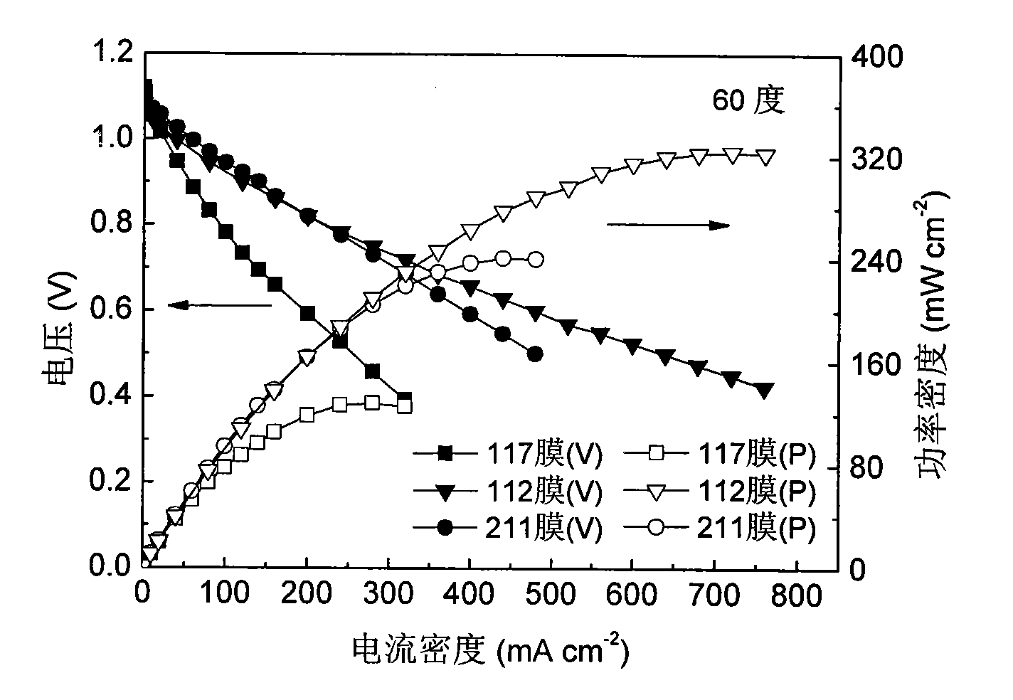
  • Fuel cell using conductive polymer modified carbon based cobaltous hydroxide composite catalyst
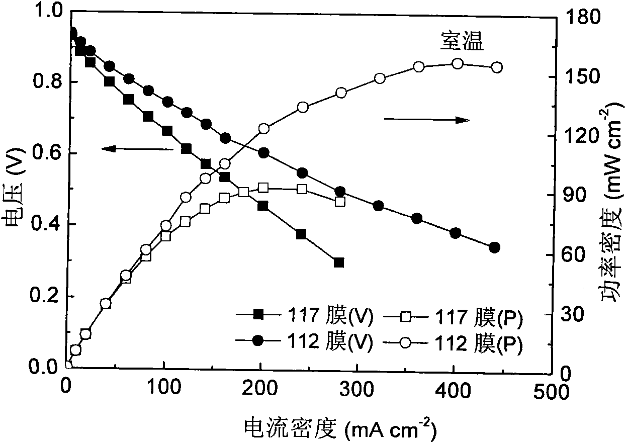
  • Fuel cell using conductive polymer modified carbon based cobaltous hydroxide composite catalyst

Examples


Embodiment 1

[0027] Add 10 g of carbon material to 100 ml of methanol to form a suspension, add 2 g of glacial acetic acid and stir at room temperature for 20 min, and adjust the pH to 1.0. Then add 2.5g pyrrole monomer and stir for 7min, then add 30ml 3wt.%FeCl 3 The aqueous solution was used as the initiator of the polymerization reaction, and stirred at room temperature for 3h. The product was washed with warm deionized water, and dried under vacuum at 90° C. for 12 hours to obtain a polypyrrole-modified carbon material with a polypyrrole content of 20 wt.%.

Embodiment 2

[0029] Add 10 grams of carbon material to 300 ml of water to form a suspension, add 5 g of glacial acetic acid and stir at room temperature for 20 minutes, and adjust the pH to 3.0. Then add 2g of pyrrole monomer and stir for 5min, then add 10ml of 30wt.%H 2 o 2 As a polymerization initiator, stir at room temperature for 3h. The product was washed with warm deionized water, and dried under vacuum at 90° C. for 12 hours to obtain a polypyrrole-modified carbon material with a polypyrrole content of 15 wt.%.

Embodiment 3

[0031] Add 10 grams of carbon material to 150 ml of water to form a suspension, add 2.5 g of glacial acetic acid and stir at room temperature for 20 minutes, and adjust the pH value to 3.0. Then add 2g thiophene monomer and stir for 10min, then add 10ml 10wt.% H 2 o 2 As a polymerization initiator, stir at room temperature for 3h. The product was washed with warm deionized water, and dried under vacuum at 90° C. for 12 hours to obtain a polypyrrole-modified carbon material with a polythiophene content of 15 wt.%.

[0032] Take 2.7 grams of polypyrrole-modified carbon material and pour it into a three-necked flask, add 40.5ml of water, quickly add 10 grams of 5.4wt.% cobalt chloride aqueous solution, heat to 80°C under reflux, and stir for 30 minutes. Slowly add 300ml reducing agent (basic sodium borohydride solution, containing 2.5-20wt.% NaBH4 and 5-20wt.% NaOH, the balance being water), vigorously stirred for 30 minutes, cooled naturally, filtered and washed, and dried in ...


PUM


Abstract

The invention relates to the fuel cell field, aims to provide a direct liquid fuel cell using conductive polymer modified carbon based cobaltous hydroxide composite catalyst. The cell comprises a negative pole using foam nickel as matrix and a positive pole using hydrophobic processed carbon paper or carbon cloth as matrix; The negative pole is made by mixing the conductive polymer modified carbon based cobaltous hydroxide composite catalyst, water, perfluoro sulfonic group resin solution with concentration of 5wt% and anhydrous ethanol, blending into slurry, coating on foam nickel and drying in air naturally. The beneficial effects of the invention is: conductive polymer can increase electrode electrical conductivity, reduce electrode impedance, improve electrode activity, and improve the electricity generation performance of cell; the synthesized conductive polymer modified carbon based cobaltous hydroxide composite catalyst is non-Pt catalyst, has a low cost, is favorable to the popularization of fuel cell technology.

Description

technical field [0001] The invention relates to the field of fuel cells, in particular to a direct liquid fuel cell using a carbon-supported cobalt hydroxide composite catalyst modified by a conductive polymer. Background technique [0002] The direct liquid fuel cell (DLFC) using the proton exchange membrane as the electrolyte can directly convert the chemical energy stored in the liquid fuel into electrical energy without going through the Carnot cycle, which is a new type of green energy technology. In addition to the advantages of high energy conversion efficiency, low emission, no pollution and no noise shared by other fuel cells, DLFC also has unique advantages: normal temperature use, simple structure, convenient fuel carrying and replenishment, and high energy density in terms of volume and weight and infrared signal is weak. It is especially suitable for small mobile and portable power sources, and has excellent potential application prospects in national defense, ...

Claims


Application Information

Patent Timeline
IPC IPC(8): H01M8/10H01M4/88H01M4/90B01J31/28B01J37/16H01M8/106
CPCY02E60/522Y02E60/50
Inventor 李洲鹏秦海英劳绍江郭岩锋
Owner ZHEJIANG UNIV
Why Eureka
Try Eureka