Adjustable microwave band-pass filter

A filter and microwave band technology, applied in waveguide devices, image communication, optical waveguide coupling, etc., can solve the problems of large volume control power consumption devices, increased process difficulty and cost, and difficulty in miniaturization, so as to reduce failure Probability, improvement of overall performance, effect of reducing microwave loss

Inactive Publication Date: 2009-12-02
BEIJING INFORMATION SCI & TECH UNIV
View PDF0 Cites 15 Cited by
  • Summary
  • Abstract
  • Description
  • Claims
  • Application Information

AI Technical Summary

Problems solved by technology

The first type of device changes the equivalent transmission line parameters of the filter by changing the polarization voltage of the dielectric material and the excitation current of the magnetic material. This type of device can withstand high microwave power and has low microwave loss, but the commonly used iron Electric body and ferrite control devices are difficult to miniaturize, and the corresponding bias circuit is complex, and static bias current needs to be maintained, so the control power consumption is very large; the second type can also withstand large microwave power, and the microwave loss is very small. However, the adjustment requires a complex servo mechanism, and the control power consumption and device volume are relatively large
Therefore, the application of the first and second types of filters is limited to microwave applications with low requirements for device miniaturization, stable power supply, high power, and non-mobile applications.
The third type of filter can achieve monolithic integration and compact structure, but because the microwave needs to be transmitted through the PN junction and semiconductor material, the corresponding microwave loss and nonlinearity will significantly affect its passband performance, and the required bias The circuit is relatively complex and often needs to be composed of multiple transistors, and it is difficult to reduce the control power consumption, so it has not been promoted at present
Its disadvantages are: 1) The transmission structure of the existing non-adjustable and conventional filter is basically used. After adding an adjustable device, the device structure is complicated and takes up a lot of chip area; 2) it is often necessary to use More than 3 switches and other regulating devices can realize the switching of the filter between the two filtering states, and realize the adjustment. When the number of switches and other devices is large, the transmission loss of the device is difficult to reduce, and the failure of a single switch causes the entire device to fail. 3) Since the bridge molds are made of electroplated or sputtered pure metal, and the on-off is achieved by the deformation of the bridge membrane, the bridge membrane is prone to fatigue, creep and other phenomena, which affects its Reliability, 4) There is a large difference in thermal expansion between the metal and the high-resistance substrate, and the structural size and reliability are greatly affected when the temperature changes greatly; 5) The structure design of the bridge mold is mainly double-ended fixed support, The driving threshold is high (complex charge pump and other booster circuits are required), and the size is close to that of traditional MIC (microwave integrated circuit) filters. High; 6) Users often need to make an electrical isolation structure between isolated high-frequency / DC control drive circuits on the same device to prevent leakage of radio frequency signals. Currently, these devices use wires composed of metal and silicon alloys to make isolation resistors , a photolithography plate needs to be made separately during processing, which increases the difficulty and cost of the process
[0009] So far, the existing dual-mode transmission line filter structure does not have the ability to adjust the filtering characteristics

Method used


Image

  • Adjustable microwave band-pass filter
  • Adjustable microwave band-pass filter
  • Adjustable microwave band-pass filter

Examples


Embodiment Construction

[0035] Below in conjunction with accompanying drawing and specific embodiment the present invention is described in further detail:

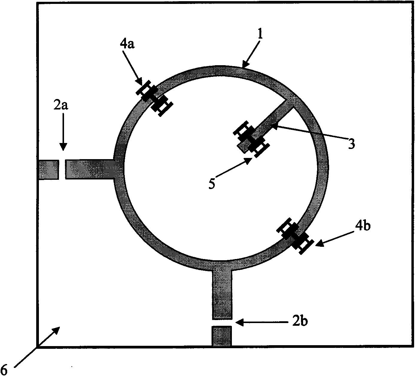
[0036] The micro-machine adjustable microwave dual-mode band-pass filter of the present invention adopts a dual-mode ring filter structure with adjustable resonance characteristics. Take the microstrip transmission line as an example to illustrate its structure and working principle.

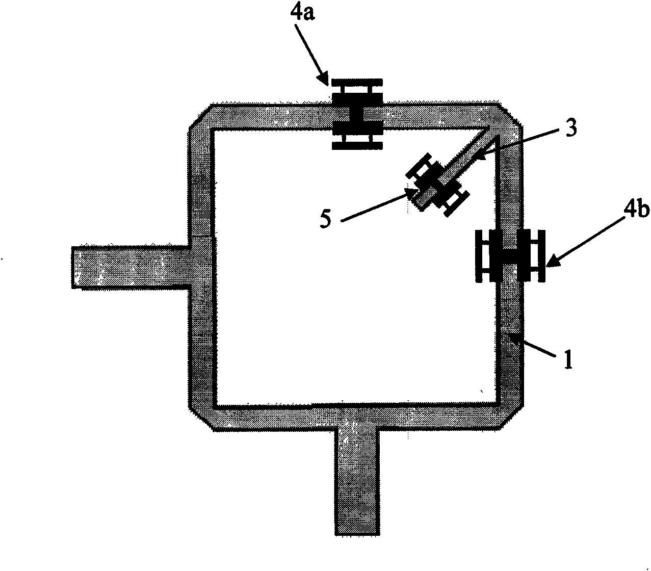
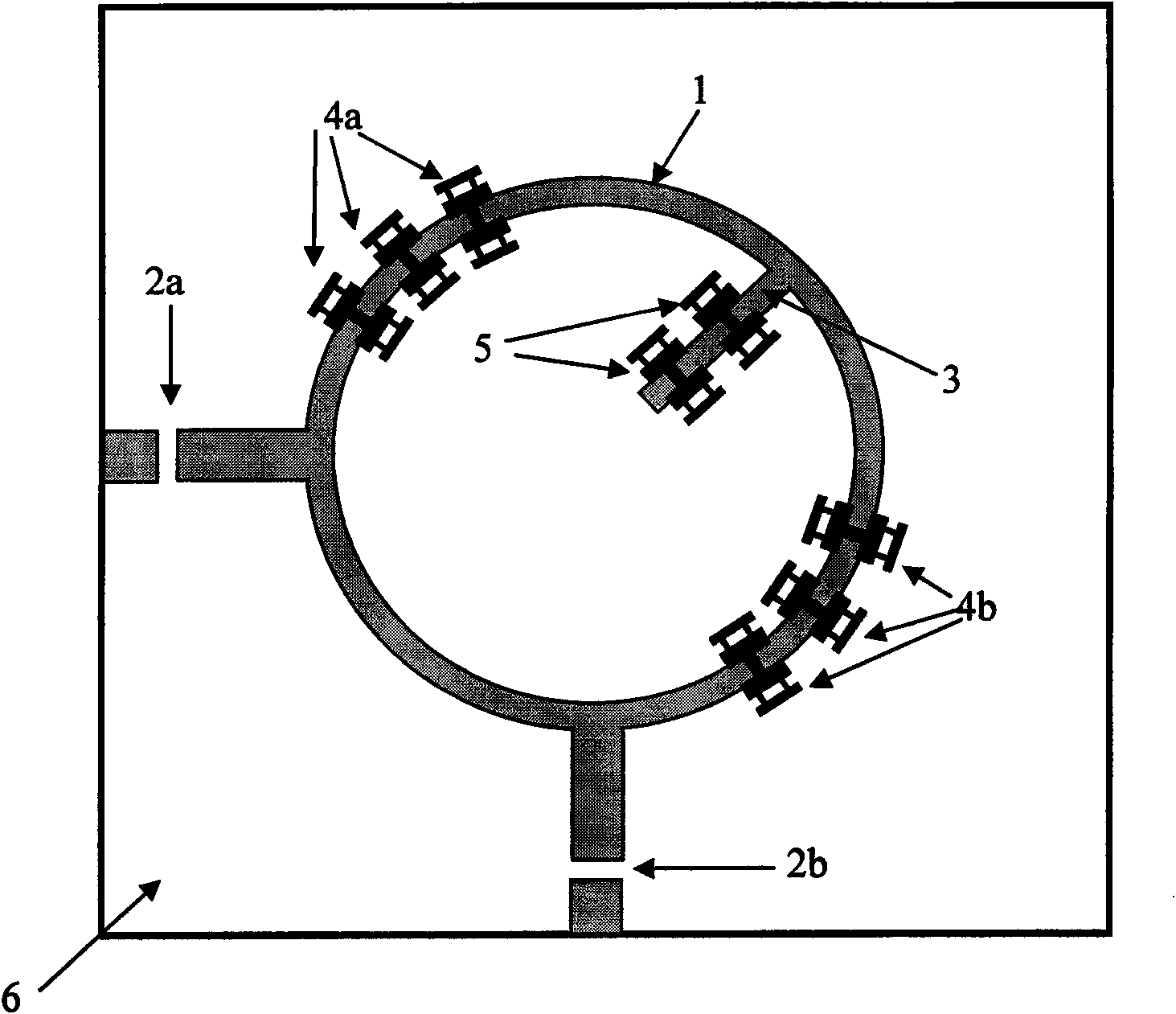
[0037] The basic circuit structure of the dual-mode filter is as figure 1 As shown, it includes a dual-mode ring resonator 1 ( figure 1 The axis of the microstrip line is a circular ring, but it can also be a square ring or a closed-loop figure with fractal characteristics), and the capacitively coupled input coupling unit 2a, output coupling unit 2b, and disturbance unit 3 play the role of central frequency adjustment The micromechanical bridging membranes 4a, 4b and the micromechanical bridging membrane 5 for adjusting the passband bandwidth. The microwave si...


PUM


Abstract

The invention discloses an adjustable microwave band-pass filter. A microwave circuit substrate is provided with a double-resonance modal annular resonator and a corresponding input coupling unit, an output coupling unit and a disturbance unit, wherein an even number of micro mechanical bridge films are placed on the resonator in a mirror symmetry mode to adjust a center frequency; and one or more micro mechanical bridge films are placed on the disturbance unit to adjust the bandwidth. The filter uses a variable capacitance effect generated by a capacitance loading structure of the micro machined bridge films to load a dual-mode resonator and a disturbance structure thereof, so that the adjustment of filtering characteristics, such as the passband center frequency, the passband bandwidth and the like can be realized by fewer micro mechanical bridge films and less chip area occupation. Compared with the prior dual-mode filter and the micro mechanical adjustable band-pass filter, the adjustable microwave band-pass filter has the advantages of more flexible structure, lower technology complexity and better device overall performance, and is suitable for filtering devices based on planar transmission lines and on-chip waveguide at the same time.

Description

technical field [0001] The invention relates to a filter device with adjustable filter characteristics such as passband frequency in the fields of radio frequency, microwave and submillimeter wave, and in particular relates to a micromechanical adjustable microwave bandpass filter based on MEMS control device. Background technique [0002] In the RF / microwave front-end circuits of wireless communication and radar systems, filters are used to filter out image frequency interference, suppress noise, and frequency division multiplexing; in high-performance oscillation, amplification, frequency multiplication, and frequency mixing circuits, The filter is used to realize the selection of a signal with a specific frequency; in addition, effective broadband impedance multiplexing, matching network and coupling structure can be realized on the basis of the filter structure. The miniaturization, broadband, mobility, and frequency agility enhancement of wireless communication equipmen...

Claims


Application Information

Patent Timeline
Patent Type & Authority Applications(China)
IPC IPC(8): H01P1/20B81B7/02
Inventor 缪旻卜景鹏
Owner BEIJING INFORMATION SCI & TECH UNIV
Why Eureka
Try Eureka