Surface-coated cutting tool

A cutting tool, surface coating technology, applied in the field of surface coating cutting tools, can solve the problems of deterioration, poor wear resistance, reduced wear resistance, etc., to achieve excellent high temperature hardness, excellent damage resistance, excellent wear resistance Effect

Active Publication Date: 2010-03-24
MITSUBISHI MATERIALS CORP
View PDF2 Cites 28 Cited by
  • Summary
  • Abstract
  • Description
  • Claims
  • Application Information

AI Technical Summary

Problems solved by technology

[0010] (a) The Al component in the (Al, Cr, Si)N layer constituting the hard coating layer of the above-mentioned conventional coated tool (refer to Patent Document 1) has an effect of increasing the high-temperature hardness, and the (Al, Cr, Si)N The Cr component in the layer has the effect of improving high-temperature toughness and high-temperature strength, and at the same time has the effect of improving high-temperature oxidation resistance in a state where Al and Cr coexist, and the Si component in the (Al, Cr, Si)N layer has The role of improving thermoplastic deformation resistance, but under severe cutting conditions such as high-speed gear cutting, high-speed milling, high-speed drilling, etc. , Insufficient high-temperature strength, so it is easy to cause chipping, breakage, etc. On the contrary, even if the content of Cr is increased to improve high-temperature toughness and high-temperature strength, the wear resistance is deteriorated due to the relative reduction of the Al content , so there are limitations in the suppression and improvement of chipping resistance and fracture resistance of the hard coating layer including (Al, Cr, Si)N layers.
[0011] (b) On the other hand, the Al component and the Si component in the (Al, Ti, Si)N layer constituting the hard coating layer of the above-mentioned conventional coated tool (refer to Patent Document 2) have the same effect as above, and, The Ti component has the effect of further improving high-temperature toughness and high-temperature strength. Therefore, even under severe cutting conditions such as the above-mentioned high-speed gear cutting, high-speed milling, and high-speed drilling, the hardness of the above-mentioned (Al, Ti, Si) N layer The coating layer also exhibits excellent chipping resistance and fracture resistance, but on the other hand, it has poor wear resistance due to insufficient high-temperature hardness and thermoplastic deformation resistance.

Method used


Image

  • Surface-coated cutting tool
  • Surface-coated cutting tool
  • Surface-coated cutting tool

Examples


Embodiment 1

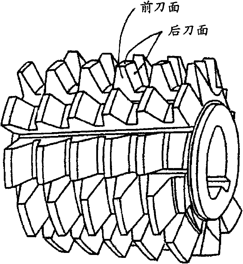
[0053] The material is made of JIS·SKH51 and JIS·SKH55 high-speed tool steel with a size of diameter: 90mm×length: 130mm, and is manufactured by machining with an overall size of outer diameter: 85mm×length: 100mm, and has four left Twisted x 16 slots in the shape of image 3 The main body (integral hob) of the high-speed steel cutting tool shown in the brief perspective view.

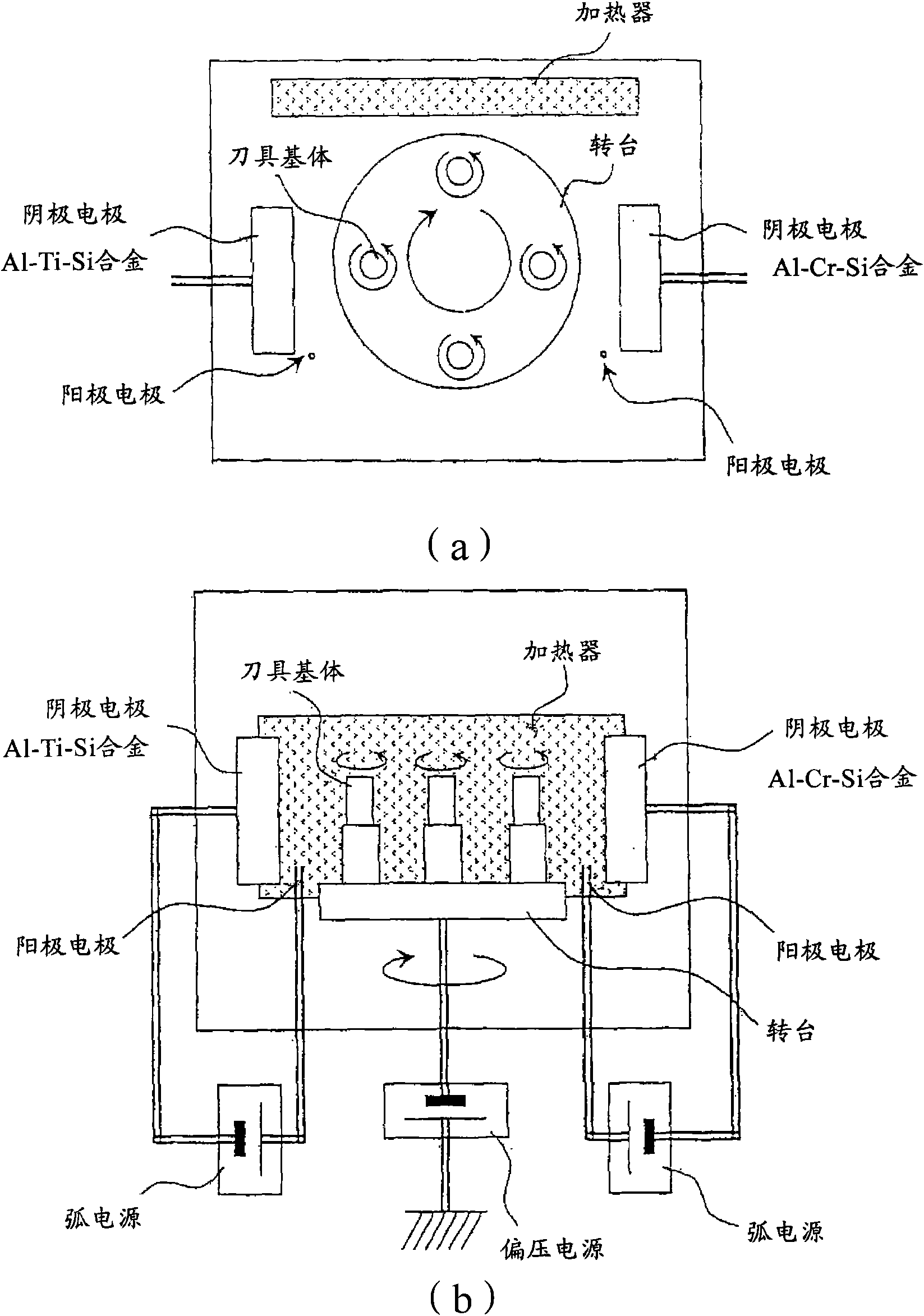
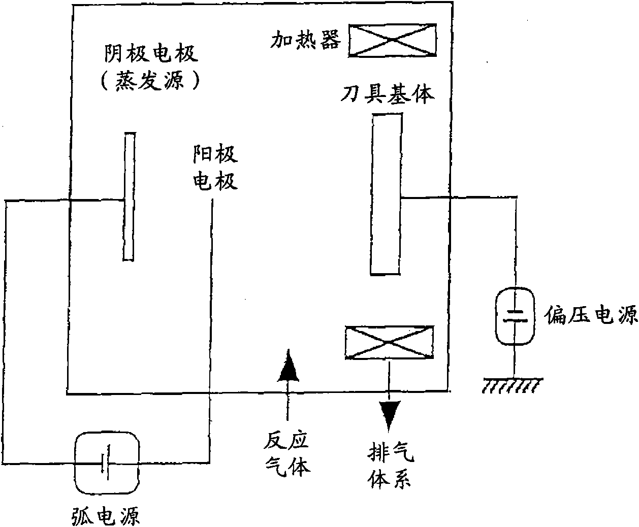
[0054] (a) Next, ultrasonically clean the main body (integral hob) of the high-speed steel gear cutting tool of the above two materials in acetone, and assemble it in a dry state along the outer periphery. figure 1 On the turntable in the shown arc ion plating apparatus, at a position at a predetermined distance from the central axis in the radial direction, the cathode electrodes (evaporation sources) facing each other across the turntable have the same characteristics as those shown in Table 1. The Al-Cr-Si alloy for forming the thin layer A having the composition corresponding to the target compos...

Embodiment 2

[0069] In addition, as the main body of the high-speed steel gear cutting tool, it is also manufactured by machining from a raw material with a size of outer diameter: 105mm×thickness: 22mm formed of high-speed tool steel made of JIS·SKH51 and JIS·SKH55, and has a pitch circle diameter: 100mm×Thickness: Overall size of 18mm, and has the shape of cutter teeth: 50 Figure 4 The disc-shaped gear shaper body base (shape 100 described in JIS·B·4356) shown in the schematic perspective view of .

[0070] Next, the surface of the above-mentioned high-speed steel gear cutter main body (gear shaper cutter) substrate is ultrasonically cleaned in acetone, and it is similarly assembled in a dry state. figure 1 In the arc ion plating device shown, under the same conditions as in the above-mentioned embodiment 1, the bottom layer of the target composition and target layer thickness shown in Table 1 is formed by vapor deposition along the layer thickness direction, and the bottom layer of th...

Embodiment 3

[0089] As raw material powders, medium-coarse WC powder with an average particle size of 5.5 μm, fine-grained WC powder with an average particle size of 0.8 μm, TaC powder with an average particle size of 1.3 μm, and NbC powder, ZrC powder with average particle diameter: 1.2 μm, Cr with average particle diameter: 2.3 μm 3 C 2Powder, VC powder with average particle size: 1.5 μm, (Ti, W)C [TiC / WC=50 / 50 in mass ratio] powder with average particle size: 1.0 μm, and average particle size: Co powder of 1.8 μm was mixed with these raw material powders in the compounding composition shown in Table 3, and wax was added and ball-milled in acetone for 24 hours. The compacts are heated up to a specified temperature in the range of 1370-1470°C at a rate of 7°C / min in a vacuum atmosphere of 6Pa, kept at this temperature for 1 hour, and then sintered under furnace cooling conditions. Three kinds of round bar sintered bodies with diameters of 8mm, 13mm, and 26mm were formed, and the above t...


PUM

PropertyMeasurementUnit
thicknessaaaaaaaaaa
depthaaaaaaaaaa
depthaaaaaaaaaa

Abstract

A surface-coated cutting tool which has excellent chipping resistance and wearing resistance in high-speed cutting processing such as high-speed gear cutting processing, high-speed milling processing,and high-speed drilling processing. The surface-coated cutting tool comprises a tool base, e.g., a cemented carbide base, cermet base, or high-speed tool steel base, and at least a hard coating layerformed on a surface of the tool base and having a multilayer structure composed of a thin layer (A) and a thin layer (B) alternating therewith. The thin layer (A) is constituted of an (Al,Cr,Si)N layer satisfying the empirical formula ¢AlXCrYSiZ!N (wherein 0.2 <= X <= 0.45, 0.4 <= Y <= 0.75, 0.01 <=Z <= 0.2, and X+Y+Z=1 in terms of atomic ratio), and the thin layer (B) is constituted of an (Al,Ti,Si)N layer satisfying the empirical formula ¢AlUTiVSiW!N (wherein 0.05 <= U <= 0.75, 0.15 <= V <= 0.94, 0.01 <= W <= 0.1, and U+V+W=1 in terms of atomic ratio).

Description

technical field [0001] The present invention relates to a hard coating layer having excellent high-temperature hardness, high-temperature toughness, high-temperature strength, and thermoplastic deformation resistance, even when used for example in high-speed gear cutting processing, high-speed milling processing, high-speed drilling processing, etc. accompanied by high heat generation. A surface-coated cutting tool (hereinafter, called a coated tool). Background technique [0002] Generally, indexable inserts, drills or micro drills, end mills, solid hobs, gear shaper cutters, and the like are known as coated tools. Indexable inserts are freely mounted on the top of the turning tool for turning or planing of various steel or cast iron workpieces; drills or micro drills are used for drilling and cutting of the above-mentioned workpieces; Milling cutters are used for plane milling, groove processing or step processing of the above-mentioned workpieces; integral hobs and gear...

Claims


Application Information

Patent Timeline
Patent Type & Authority Applications(China)
IPC IPC(8): B23B27/14B23B51/00B23C5/16B23F21/00C23C14/06
CPCC23C14/0021C23C28/42B23F21/00C23C28/044C23C28/04C23C14/0641C23C30/005Y10T407/17Y10T407/1948Y10T408/78Y10T428/24975Y10T428/265
Inventor 前田浩一森川正宣松冈勇树一宫夏树
Owner MITSUBISHI MATERIALS CORP
Why Eureka
Try Eureka