Quick thermal treatment method for preparing vanadium dioxide film

A technology of rapid heat treatment and vanadium oxide thin film, applied in ion implantation plating, metal material coating process, coating, etc., to achieve high repeatability, efficient heat treatment method, and optimization of rapid heat treatment conditions

Inactive Publication Date: 2011-10-12
TIANJIN UNIV
View PDF3 Cites 20 Cited by
  • Summary
  • Abstract
  • Description
  • Claims
  • Application Information

AI Technical Summary

Problems solved by technology

[0006] There is no report on the technology of using rapid heat treatment to

Method used


Image

  • Quick thermal treatment method for preparing vanadium dioxide film
  • Quick thermal treatment method for preparing vanadium dioxide film
  • Quick thermal treatment method for preparing vanadium dioxide film

Examples


Embodiment 1

[0028] (1) Cut the silicon wafer into a square substrate with a size of 2cm×2cm, soak it in absolute ethanol, clean it ultrasonically for 10 minutes, rinse it with deionized water, and dry it;

[0029] (2) Place the silicon substrate cleaned in step 1) in a vacuum chamber, and evacuate the body to 2.5×10 -4 Pa. Introduce argon and oxygen, the flow rates of argon and oxygen are 30sccm and 0.8sccm respectively; start sputtering when the working pressure is adjusted to 1.0Pa, and the sputtering time is 15 minutes;

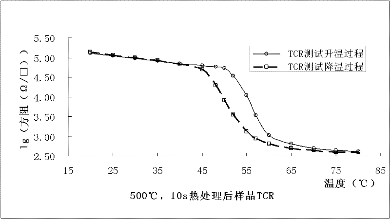
[0030] (3) Put the sample in step 2) into a rapid annealing furnace, set the annealing temperature to 500°C; the heating rate to 50°C / s; and the holding time to 10s. The protective gas nitrogen (mass purity is 99.999%) flow rate is 10 slpm when the temperature is lowered, and the nitrogen flow rate is 3 slpm when the temperature is raised and kept warm;

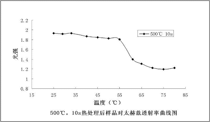
[0031] (4) Measure the temperature coefficient of resistance (TCR) and terahertz transmittance of the sample, su...

Embodiment 2

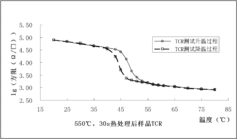
[0033] The operation steps are the same as in Example 1, and the process conditions are correspondingly changed as follows: the flow rates of argon and oxygen are 55 sccm and 1.3 sccm respectively; the working pressure is 2.0 Pa; the sputtering time is 30 minutes; the annealing temperature is 550° C., and the holding time is 30 s.

[0034] Measure the temperature coefficient of resistance (TCR) and terahertz transmittance curve of the sample, such as image 3 and Figure 4 . It can be seen from the figure that the phase transition point obviously moves to a lower temperature, which is 47°C, which is closer to room temperature. Generally, the reduction of the phase transition point can be achieved by doping vanadium dioxide, but now it can be achieved by changing the conditions of rapid heat treatment.

[0035] Implementation 3

[0036] The operation steps are the same as in Example 1, and the process conditions are correspondingly changed as follows: the flow rates of argon...


PUM


Abstract

The invention discloses a quick thermal treatment method for preparing a vanadium dioxide film. The method comprises the following steps of: (1) cutting a silicon chip to form a substrate, and cleaning and drying the silicon substrate; (2) placing the silicon substrate of the step (1) in a vacuum chamber, and depositing a vanadium dioxide film on the silicon substrate by adopting a target magnetron sputtering method, wherein the target is 99.99 percent metallic vanadium, argon is used as a working gas and oxygen is used as a reaction gas; (3) putting the vanadium dioxide film product sputtered in the step (2) into a quick annealing furnace to prepare a vanadium dioxide film, wherein the annealing temperature is 500 to 550 DEG C, the heating rate is 50 DEG C per second, the heat preservation time is 10 to 30 seconds, cooling is performed within 3 minutes, and the protective gas is nitrogen; and (4) measuring. By the method, the thermal treatment time is shortened, and obvious phase change property can be obtained after the vanadium dioxide film product is quickly and thermally treated for 10 to 30 seconds; the method is simple in process control, high in repeatability and suitable for large-area production; and electric and optical properties of the vanadium dioxide film are optimized. The method is widely applied in the fields of infrared detectors, memories, optical communications and the like.

Description

technical field [0001] The invention relates to heat treatment of thin films, in particular to a method for rapid heat treatment of vanadium oxide thin films. Background technique [0002] Vanadium dioxide is a thermosensitive and photosensitive material. Vanadium dioxide is a monoclinic rutile structure at low temperature; it transforms into a tetragonal rutile structure at a high temperature, and the phase transition temperature is 68°C. Reversible mutations will occur in the resistivity, magnetic susceptibility and light transmittance of vanadium dioxide near the phase transition point. Due to these characteristics of vanadium dioxide, it has a wide range of applications in infrared detectors, memory, optical communication, and smart windows. [0003] The methods for preparing vanadium dioxide thin films mainly include magnetron sputtering, evaporation, sol-gel and pulsed laser deposition. The obtained vanadium dioxide samples need to be heat-treated to have phase-chan...

Claims


Application Information

Patent Timeline
IPC IPC(8): C23C14/08C23C14/35
Inventor 胡明后顺保吕志军陈涛梁继然
Owner TIANJIN UNIV
Why Eureka
Try Eureka