Method for preparing oriented graphene nanoribbon (GNR) array

A graphene nanoribbon and array technology, applied in the field of graphene material preparation, can solve the problems of difficult device integration and difficult GNR device performance, and achieve low in-plane defect density, good electrical conductivity, and low edge disorder. Effect

Inactive Publication Date: 2012-10-31
SUZHOU INST OF NANO TECH & NANO BIONICS CHINESE ACEDEMY OF SCI
View PDF4 Cites 18 Cited by
  • Summary
  • Abstract
  • Description
  • Claims
  • Application Information

AI Technical Summary

Problems solved by technology

Based on the above, the current method of preparing GNRs has the following insurmountable problems: the randomness of the arrangement of GNRs makes it difficult to integrate devices in the future; the wide GNRs mak

Method used


Image

  • Method for preparing oriented graphene nanoribbon (GNR) array
  • Method for preparing oriented graphene nanoribbon (GNR) array
  • Method for preparing oriented graphene nanoribbon (GNR) array

Examples


Embodiment 1

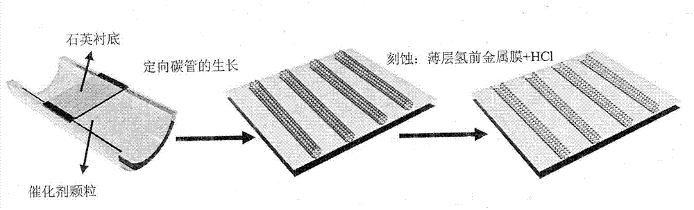
[0033] Embodiment 1 For the technical process of this embodiment, please refer to Figure 1a , which includes the following steps:

[0034] (1) The substrate material is a single-sided polished, constant temperature cut (ST-cut) single crystal quartz plate, where the positioning side X is perpendicular to one side of the quartz plate, the Y deviation Z is 42.75°, and the cutting deviation angle is less than ±0.3° . The substrate was ultrasonically cleaned with acetone, ethanol, and deionized water for 5 min respectively), and then dried with nitrogen. The cleaned substrate was annealed at 800° C. for 8 hours in an air atmosphere, and then cooled naturally. Finally, the annealed quartz substrate was ultrasonically cleaned with ethanol and deionized water again and dried with nitrogen.

[0035] (2) Firstly, metal chloride (CuCl 2 ) ethanol solution was dropped on the quartz boat (drop 80 μL). The quartz boat was heated to 450 °C for 25 min in an air atmosphere to oxidize the...

Embodiment 2

[0037] Embodiment 2 The technological process of the present embodiment please be close to embodiment 1, and it comprises the following steps:

[0038] (1) The substrate material is a single-sided polished, constant temperature cut (ST-cut) single crystal quartz plate, where the positioning side X is perpendicular to one side of the quartz plate, the Y deviation Z is 42.75°, and the cutting deviation angle is less than ±0.3° . The substrate was ultrasonically cleaned with acetone, ethanol, and deionized water for 1 min respectively), and then dried with nitrogen. The cleaned substrate was annealed at 800° C. for 1 hour in an air atmosphere, and then cooled naturally. Finally, the annealed quartz substrate was ultrasonically cleaned with ethanol and deionized water again and dried with nitrogen.

[0039] (2) First, metal chloride (NiCl 2 ) ethanol solution was dropped on the quartz boat (drop 100 μL). The quartz boat was heated to 400 °C for 25 min in an air atmosphere to o...

Embodiment 3

[0041] Embodiment 3 The technological process of the present embodiment please be close to embodiment 1, and it comprises the following steps:

[0042] (1) The substrate material is a single-sided polished, constant temperature cut (ST-cut) single crystal quartz plate, where the positioning side X is perpendicular to one side of the quartz plate, the Y deviation Z is 42.75°, and the cutting deviation angle is less than ±0.3° . The substrate was ultrasonically cleaned with acetone, ethanol, and deionized water for 10 min respectively), and then dried with nitrogen. The cleaned substrate was annealed at 850° C. for 10 hours in an air atmosphere, and then cooled naturally. Finally, the annealed quartz substrate was ultrasonically cleaned with ethanol and deionized water again and dried with nitrogen.

[0043] (2) Firstly, metal chloride (FeCl 3 ) ethanol solution was dropped on the quartz boat (drop 80 μL). In the air atmosphere, the quartz boat was heated to 600 °C for 60 mi...


PUM


Abstract

The invention discloses a method for preparing an oriented graphene nanoribbon array. As one of optimized schemes, the method includes the following steps of (1) depositing nano-metal catalyst particles on a substrate surface which is subjected to a polishing process; (2) growing a directionally distributed carbon nanotube on the substrate surface; (3) depositing a thin layer hydrogen front metal film on the substrate surface; and (4) processing the substrate surface with an acid solution and dissecting the carbon nanotube along the axial direction to form the graphene nanoribbon array. The method for preparing the oriented graphene nanoribbon array has the advantages that the process is simple, the method is easy to implement, the prepared GNR has a high directionality, a high density, low in-plane defect density and edge disorder and a high electron mobility, the density and the like of the GNR array can be controlled through a growth technology and an etching process of a directional carbon tube, simultaneously a device based on the GNR array has a good electrical conduction performance, and the method has a significant application prospect in fields of spintronics, sensors, transistors and the like.

Description

technical field [0001] The invention relates to a method for preparing graphene materials, in particular to a method for preparing graphene nanobelts by chemical reaction etching. Background technique [0002] Graphene nanoribbons (GNRs) possess novel electronic and spin-conducting properties, such as quantum-confined band gaps and edge magnetic ordering, and are expected to have important applications in field-effect transistors, spintronics, and sensors. , so it has attracted more and more attention from researchers. Currently, there are three main methods to fabricate GNRs: 1) bottom-up assembly; 2) photolithography or plasma etching of graphite and carbon nanotubes (CNTs); 3) strong oxidation or gas expansion to split multi-walled carbon nanotubes. Tube. Among these methods, dissection of multi-walled carbon nanotubes (MOL.LWNTs) provides a promising way to fabricate narrow-width GNRs. However, in-plane defects and rough edges of GNRs may be caused by photolithography...

Claims


Application Information

Patent Timeline
IPC IPC(8): C01B31/04B82Y30/00C01B32/184
Inventor 刘立伟龚佑品龙明生高嵩朱超耿秀梅
Owner SUZHOU INST OF NANO TECH & NANO BIONICS CHINESE ACEDEMY OF SCI
Why Eureka
Try Eureka