
A micro-injection mold for biodegradable vascular stent

A vascular stent and micro-injection technology, which is applied in the field of micro-injection molds for biodegradable vascular stents, can solve the problems of difficult control of solder joints, complex winding structure, and affecting the deformation performance of stents, so as to ensure the overall strength and fatigue performance and avoid production. Low efficiency, avoiding the effect of poor surface quality

Inactive Publication Date: 2014-10-15
DALIAN UNIV OF TECH
View PDF3 Cites 0 Cited by
  • Summary
  • Abstract
  • Description
  • Claims
  • Application Information

AI Technical Summary

Problems solved by technology

Due to the relatively complex winding structure and technical difficulties such as difficult automation of the process, wire winding becomes difficult to realize
The screen after photochemical etching is relatively soft, and it is easy to twist and deform during the rolling process. At the same time, it is difficult to control the solder joints, which will cause the asymmetry of the overall mechanical properties of the stent and affect the deformation performance of the stent.
Although laser cutting is now commonly used as a method for forming vascular stents, there are unavoidable problems such as heat-affected zones and insufficient surface quality, and subsequent cumbersome processing techniques are required, which increases the production cost of vascular stents, thus causing Vascular stents are expensive and unaffordable for many consumers

Method used


Image

  • A micro-injection mold for biodegradable vascular stent
  • A micro-injection mold for biodegradable vascular stent
  • A micro-injection mold for biodegradable vascular stent

Examples


Embodiment Construction

[0020] Specific embodiments of the present invention will be described in detail below in conjunction with technical solutions and accompanying drawings.

[0021] Injection molding biodegradable polymer vascular stent, the concrete steps of embodiment are as follows:

[0022] step 1

[0023] Use a drying oven to dry the biodegradable polymer material at a certain temperature to remove moisture.

[0024] step 2

[0025] Install the biodegradable polymer stent mold on the injection molding machine and start the vacuum pump.

[0026] step 3

[0027] Start the mold temperature machine, and heat the mold before filling through the heating oil channel.

[0028] step 4

[0029] Add a certain amount of dried biodegradable polymer material into the hopper of the injection molding machine, and set the process parameters such as melt temperature, injection volume, injection rate and injection pressure required for the injection molding process.

[0030] step 5

[0031] The polymer...


PUM


Abstract

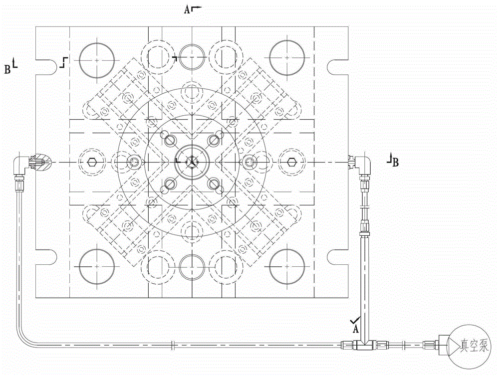
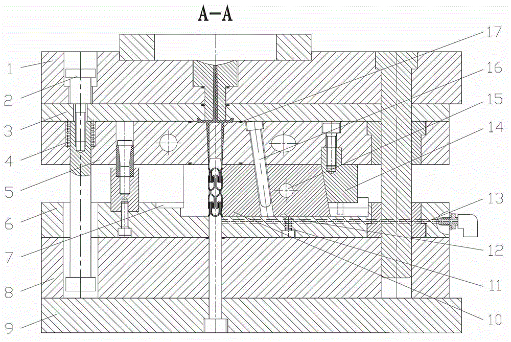
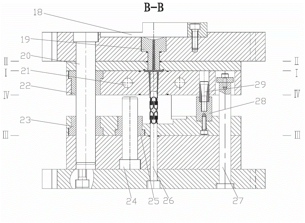
The invention discloses a micro injection mould for a biodegradable vascular stent and belongs to the technical field of polymer injection moulds. The micro injection mould for the biodegradable vascular stent is characterized by adopting a single-cavity injection mould with a split type mould cavity structure, four-time parting, multi-point sprue feeding and multiway sequential core pulling of an inclined sliding block, wherein the single-cavity injection mould comprises a mould frame part, a side parting part, a mould temperature control part and a vacuumizing part; and the micro injection mould for the biodegradable vascular stent mainly comprises a positioning ring, a sprue sleeve, a fixed mould fixed plate, a demoulding runner plate, a fixed template, a moveable template, a pad plate, a moveable mould fixed plate, a sliding block, a sliding block pressing plate, a limited steel ball, a wedge block, an inclined guide column, a mould core, a heating oil channel, a cooling water channel, a sealing ring, a limited rod, a spring, a guide column, a guide sleeve, a nylon sleeve fixed block and a nylon sleeve. The micro injection mould for the biodegradable vascular stent has the beneficial effects of forming the vascular stent at one step, guaranteeing the size precision, the surface quality, the integral strength and the fatigue performance required by the stent, realizing automatic production, improving the production efficiency and reducing the manufacturing cost of the vascular stent.

Description

technical field [0001] The invention belongs to the technical field of polymer injection molds, and relates to a micro-injection mold for biodegradable vascular stents. Background technique [0002] Vascular stent is the core device of percutaneous transluminal coronary angioplasty, and percutaneous transluminal coronary angioplasty is under the guidance of medical imaging equipment. The inflation of the balloon makes the stent expand. After the balloon is withdrawn, the stent can continue to support the diseased blood vessel to ensure the smooth flow of blood. It is an interventional therapy for the treatment of coronary artery or peripheral atherosclerosis. [0003] Vascular stents have mainly experienced the development process from bare metal stents to biodegradable metal stents. The rejection of bare metal stents and secondary operations increase the difficulty of treatment, while biodegradable metal stents have a high probability of thrombosis and restenosis , the eff...

Claims


Application Information

Patent Timeline
Patent Type & Authority Patents(China)
IPC IPC(8): B29C45/26B29C45/73
Inventor 赵丹阳顿锁王敏杰
Owner DALIAN UNIV OF TECH
Learn More