Thin-film material for near field communication (NFC) equipment, and preparation method and application for thin-film material

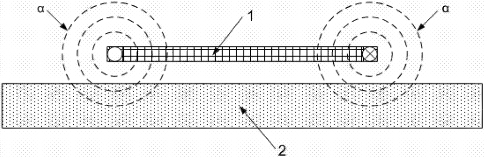
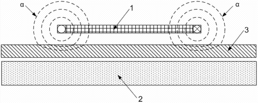
A thin-film material and equipment technology, which is applied in the field of thin-film materials for NFC equipment and its preparation, can solve problems such as eddy current loss, induced alternating electromagnetic signal eddy current loss, and entry into the interior of the metal backplane 2, so as to avoid eddy current loss and improve accuracy. Sex, the effect of good electromagnetic performance

Active Publication Date: 2013-01-30
BEIKUANG MAGNETS FUYANG CO LTD
View PDF3 Cites 6 Cited by
  • Summary
  • Abstract
  • Description
  • Claims
  • Application Information

AI Technical Summary

Problems solved by technology

In the prior art, the internal space of the NFC mobile phone is very limited, so various metal structural parts such as battery casings, circuit boards, and metal back plates are inevitably arranged around the antenna of the NFC mobile phone; The ability of electromagnetic interference, so in the process of transmitting the induced alternating electromagnetic signal through the antenna, the metal structure around the antenna will cause the induced alternating electromagnetic signal to generate eddy current loss, which will cause the NFC chip to fail to read and write data; for example :like figure 1 As shown, the schematic diagram of the signal transmission principle of an existing NFC mobile phone, in the process of transmitting the induced alternating electromagnetic signal α through the antenna 1, the induced alternating electromagnetic signal α sent by the two ends of the antenna 1 will be transmitted to the metal backplane 2, Since the metal backplane 2 does not have the ability to resist electromagnetic interference, the induced alternating electromagnetic signal α will enter the inside of the metal backplane 2 and cause eddy current loss

Method used


Image

  • Thin-film material for near field communication (NFC) equipment, and preparation method and application for thin-film material
  • Thin-film material for near field communication (NFC) equipment, and preparation method and application for thin-film material
  • Thin-film material for near field communication (NFC) equipment, and preparation method and application for thin-film material

Examples


preparation example Construction

[0069] (2) A preparation method of thin film material for NFC equipment

[0070] Such as Figure 4 Shown, a kind of preparation method of film material for NFC equipment, it specifically can comprise the following steps:

[0071] Step A: preparing flake-shaped iron-silicon-based alloy powder.

[0072] Wherein, the corresponding flake-shaped Fe-Si-based alloy powder can be at least one of sendust-silicon flake-shaped powder, sendust-chromium flake-shaped powder or sendust-aluminum-chromium flake-shaped powder, and these flake-shaped ferrosilicon The base alloy powder preferably satisfies the technical parameter conditions in Table 1 to Table 6 above.

[0073] Specifically, the corresponding sheet-shaped iron-silicon-based alloy powder can be prepared by the following preparation process:

[0074] Step a1, metal smelting: batching is carried out according to the component contents in Table 1, Table 3 or Table 5 above, and put into vacuum melting equipment to melt into alloy i...

Embodiment 1

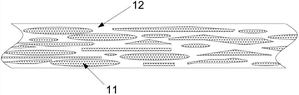
[0099] Iron, silicon and aluminum are mixed according to the ratio of Fe: Si: Al = 85: 10: 5, and after vacuum smelting, ingot making and atomization powder making, the alloy powder with a particle size of 50-150 μm is obtained; the obtained The alloy powder is processed by a flake processor for 4 to 10 hours, and then winnowed and tempered to obtain the sendust with a particle size of 50 to 150 μm, a powder thickness of ≤1.2 μm, and a powder diameter to thickness ratio of ≥450. Flake powder.

[0100] Mix the above sendust flake powder with silane coupling agent and alcohol according to the ratio of sendust flake powder: silane coupling agent: alcohol = 100:1:100, fully stir and dry to obtain coating Good sendust flake powder;

[0101] Mix the above-coated sendust flake powder and polyurethane adhesive according to the ratio of coated sendust flake powder: polyurethane adhesive = 85:15, and extrusion-coat on the PET plastic film. Cloth; apply a 400-500Gs unidirectional magne...

Embodiment 2

[0104] Iron, silicon and chromium are mixed according to the ratio of Fe: Si: Cr = 88: 10: 2, after vacuum melting ingot making and atomization powder making, the alloy powder with a particle size of 50-100 μm is obtained; the prepared The alloy powder is processed by a flake processor for 4 to 10 hours, and then winnowed and tempered to obtain iron silicon chromium with a particle size of 50 to 150 μm, a powder thickness of ≤1.2 μm, and a powder diameter to thickness ratio of ≥450. Flake powder.

[0105] Mix the above iron silicon chromium sheet powder with silane coupling agent and alcohol according to the ratio of iron silicon chromium sheet powder: silane coupling agent: alcohol = 100:1:100, fully stir and dry to obtain coating Good FeSiCr flake powder;

[0106] Put the above-coated ferrosilicon chromium flake powder with polyurethane adhesive and epoxy resin adhesive, according to the ratio of coated ferrosilicon chromium flake powder: polyurethane adhesive: epoxy resin ...


PUM

PropertyMeasurementUnit
thicknessaaaaaaaaaa
thicknessaaaaaaaaaa
thicknessaaaaaaaaaa

Abstract

The invention relates to a thin-film material for near field communication (NFC) equipment, and a preparation method and application for the thin-film material. The thin-film material is formed by compounding a polyethylene terephthalate (PET) plastic film and sheet ferro-silicon-based alloy powder serving as a base material; and the sheet ferro-silicon-based alloy powder is adhered to the surface of the PET plastic film and is parallel to the PET plastic film. By an embodiment of the invention, a phenomenon that inductive alternate electromagnetic signals are affected by metal structural parts and then eddy current loss is caused is avoided, and the accuracy, the sensitivity and the read-write distance in data reading and writing of an NFC chip are increased.

Description

technical field [0001] The invention relates to the field of anti-electromagnetic interference materials, in particular to a thin film material for NFC equipment and a preparation method and application thereof. Background technique [0002] In recent years, with the continuous development of radio frequency identification technology, near-field communication (the English full name of near-field communication is Near Field Communication, usually abbreviated as NFC) technology has become a new hot technology that has sprung up suddenly. Near-field communication technology (NFC technology), also known as short-range wireless communication technology, is a short-range non-contact identification and interconnection technology that allows non-contact point-to-point data transmission between electronic devices, and its use distance is less than or Equal to 0.1 meters, it is mainly used in electronic equipment such as digital cameras, computers, mobile phones, and PDAs. Since NFC ...

Claims


Application Information

Patent Timeline
Patent Type & Authority Applications(China)
IPC IPC(8): H01B5/14H01B1/02H01B13/00H05K9/00
Inventor 陶振声范学伟高磊邹科迟百强吕宝顺廖有良连江滨王倩
Owner BEIKUANG MAGNETS FUYANG CO LTD
Why Eureka
Try Eureka