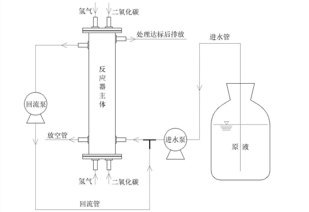
Backflow type hydrogen matrix bio-membrane reactor with carbon dioxide serving as carbon source
A technology of biofilm reactor and carbon dioxide, which is applied in the field of treatment of oxidative pollutants, can solve the problems of non-degradable phosphate, easily damaged membrane components, and inhibition of microbial activities, so as to avoid the precipitation of hardness ions, avoid overflow and waste , the effect of increasing the contact area
- Summary
- Abstract
- Description
- Claims
- Application Information
AI Technical Summary
Problems solved by technology
Method used
Image

Examples
Embodiment Construction
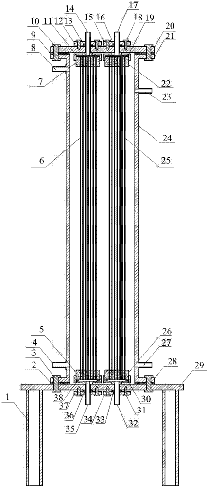
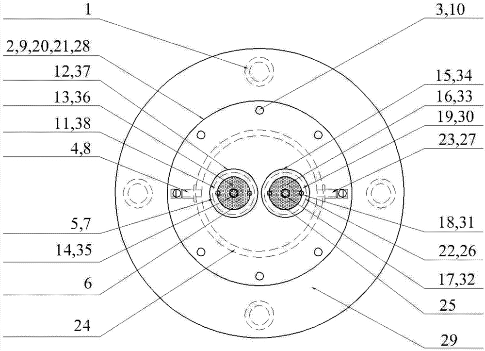
[0029] Firstly, the reactor cylinder is made. The reactor cylinder 24, the upper end flange 21 and the lower end flange 28 are all made of plexiglass material and connected as a whole by welding process. The flange base 29 and the bracket 1 are also made of The welding process connects together. Then holes are punched at corresponding positions of the reactor cylinder 24, and short pipes are welded to serve as the water outlet 8, the water inlet 27, the return port 23 and the vent 4 respectively.
[0030] Then proceed to 1 # and 2 # Assembly of membrane modules. 1 # H through the inside of the membrane module 2 , by the upper end hydrogen pipe internal thread sleeve 14, the lower end hydrogen pipe internal thread sleeve 35, the upper end hydrogen leak-proof gasket 11, the lower end hydrogen gas leak-proof gasket 38,1 # Externally threaded sleeve 7, 1 at the upper end of the membrane module # The externally threaded sleeve 5 at the lower end of the membrane module and the...
PUM
| Property | Measurement | Unit |
|---|---|---|
| pore size | aaaaa | aaaaa |
| pore size | aaaaa | aaaaa |
Abstract
Description
Claims
Application Information
 - R&D
- Intellectual Property
- Life Sciences
- Materials
- Tech Scout
- Unparalleled Data Quality
- Higher Quality Content
- 60% Fewer Hallucinations
Browse by: Latest US Patents, China's latest patents, Technical Efficacy Thesaurus, Application Domain, Technology Topic, Popular Technical Reports.
© 2025 PatSnap. All rights reserved.Legal|Privacy policy|Modern Slavery Act Transparency Statement|Sitemap|About US| Contact US: help@patsnap.com