Oil-containing sludge treatment method and process flow

A sludge treatment and sludge technology, which is used in dewatering/drying/concentrating sludge treatment, petroleum industry, pyrolysis treatment of sludge, etc. Failure to meet environmental protection requirements and other issues, to achieve the effect of low freezing point, good oil quality, and environmental protection

Active Publication Date: 2013-06-05
RES INST OF SHAANXI YANCHANG PETROLEUM GRP
View PDF5 Cites 21 Cited by
  • Summary
  • Abstract
  • Description
  • Claims
  • Application Information

AI Technical Summary

Problems solved by technology

Oily sludge is a hazardous solid waste. For this reason, major domestic oil fields and refining and chemical companies have strengthened the research on oily sludge treatment technology, and research departments such as universities and colleges have also participated in it. Although a variety of oily sludge has been developed Treatment methods and processes, such as: incineration, pyrolysis, extraction, biological methods, etc., but due to the limitations of treatment costs, required process conditions and other factors, the actual industrial application of the research results is not much, and most domestic oil fields still use landfill method to treat oily sludge, and the landfill is not up to standard. A few oilfields use methods such as supergravity solid-liquid separation and ultrasonic radiation treatment to recover crude oil, but the oil content of oily sludge after treatment still does not meet environmental protection requirements.

Method used


Image

  • Oil-containing sludge treatment method and process flow

Examples


Embodiment 1

[0027] Example 1: Treatment of oilfield crude oil storage tank bottom sludge

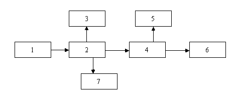
[0028] 1. Add sodium hydroxide to the oily sludge with a water content greater than 70% to adjust the pH value to 7.5, then add 200 mg / L of polyaluminum chloride and 5 mg / L of cationic polyacrylamide, and then enter the dehydration device 1 for dehydration treatment. The moisture content of the sludge after dehydration is 68.4%;

[0029] 2. The dehydrated oily sludge enters the pyrolysis device 2 for pyrolysis at 400°C, and the reaction time is 1.5 hours; only 40%-50% of the crude oil contained in the oily sludge is recovered (that is, the recovered crude oil accounts for 40-50% of the total crude oil content in the sludge);

[0030] 3. The cracked gas produced by pyrolysis enters the gas recovery device 3 for recycling;

[0031] 4. The oil and water produced by pyrolysis enter the oil-water separation device 4 for oil-water separation, the separated oil enters the oil storage tank 5 for recycling...

Embodiment 2

[0037] Example 2: Treatment of Oily Sludge in Crude Oil Storage Tanks of Refinery

[0038] 1. Add sodium hydroxide to the oily sludge with a water content greater than 70% to adjust the pH value to 7.5, then add 200 mg / L of polyaluminum chloride and 5 mg / L of cationic polyacrylamide, and then enter the dehydration device 1 for dehydration treatment. The moisture content of the sludge after dehydration is 66.7%;

[0039] 2. The oily sludge after dehydration enters the pyrolysis device 2, and is pyrolyzed at a low temperature at 380°C. The reaction time is 1.5 hours; only 40%-50% of the crude oil contained in the oily sludge is recovered (ie: recovered crude oil Accounting for 40-50% of the total crude oil content of oily sludge);

[0040] 3. The cracked gas produced by pyrolysis enters the gas recovery device 3 for recycling;

[0041] 4. The oil and water produced by pyrolysis enter the oil-water separation device 4 for oil-water separation, the separated oil enters the oil s...

Embodiment 3

[0047] Example 3: Treatment of Oily Sludge in Refinery Sludge Pool

[0048] 1. Add hydrochloric acid to the oily sludge with a water content greater than 70% to adjust the pH value to 7.0, then add 200 mg / L of polymeric iron and 5 mg / L of cationic polyacrylamide, and then enter the dehydration device 1 for dehydration treatment. After the oily sludge is dehydrated Moisture content is 65.8%;

[0049] 2. The dehydrated oily sludge is pyrolyzed at 300°C, and the reaction time is 1 hour;

[0050] 3. The residual pyrolysis sludge is made by adding 30% coke, 0.01% potassium chlorate, 0.5% lime clinker and 0.5% calcium oxide (magnesia or zinc oxide) into the fuel preparation device. For the use of fuel particles, the above percentages are all mass percentages.

[0051] After the above steps, the test results of the oily sludge in the crude oil storage tank of the refinery are shown in Table 3:

[0052] Table 3 Test results after treatment of oily sludge in refinery sludge pool

...


PUM


Abstract

The invention belongs to an oil-containing sludge treatment method, and particularly relates to a method and process flow for treating oil-containing sludge having an oil content of more than 10%. The method is characterized by comprising the following steps: for oil-containing sludge having a water content of more than 70%, adding pH regulator, and regulating the pH value to 7-8; adding inorganic flocculant and organic flocculant, and performing dehydration treatment; after dehydration, feeding the oil-containing sludge into a pyrolysis device, performing low-temperature pyrolysis, and feeding gas generated by the pyrolysis into a gas recovery device for recycling; performing oil-water separation on the generated oil and water through an oil-water separation device, feeding the separated oil into an oil storage tank for recycling, and feeding the separated water into a sewage treatment device or an oilfield water treatment system; and adding igniter, combustion improver, binder and desulfurizer into the remaining sludge after the pyrolysis, feeding into a fuel preparation device, and preparing into fuel for utilization. The invention solves the technical problem on oil-containing sludge treatment for oilfield and refinery enterprises, and achieves the purposes of effectively recycling resources, saving energy, reducing emission and protecting environment.

Description

technical field [0001] The invention belongs to a treatment method for oily sludge, in particular to a treatment method and process flow for oily sludge with an oil content greater than 10%. Background technique [0002] A large amount of oily sludge will inevitably be produced in the process of exploration, development, storage and transportation in oil fields and in the refining process of refining and chemical enterprises. These oily sludges have the characteristics of complex composition, large changes in oil content, and difficult treatment. Improper use not only seriously pollutes groundwater, surface water and the surrounding environment, but also causes waste of oil resources. [0003] At present, our country has strengthened the work of environmental protection. According to the "Management Measures for the Collection Standards of Sewage Discharge Fees", the disposal of hazardous wastes in landfills does not comply with the relevant national regulations. The standar...

Claims


Application Information

Patent Timeline
Patent Type & Authority Applications(China)
IPC IPC(8): C02F11/10C02F11/14C10L5/46
CPCY02E50/30Y02E50/10
Inventor 杨志刚高瑞民屈撑囤刘立张世君李建东何飞张永强汶锋刚
Owner RES INST OF SHAANXI YANCHANG PETROLEUM GRP
Why Eureka
Try Eureka