Method for preparing diffraction micro-optical elements based on mask lithography technique and injection molding
A lithography technology and injection molding technology, applied in the field of manufacturing diffractive micro-optical elements based on mask lithography technology and injection molding, can solve the problems of inability to manufacture fine-structure micro-optical elements, low yield, long processing cycle, etc. Achieve the effect of low cost per piece, high yield and shortened production cycle
- Summary
- Abstract
- Description
- Claims
- Application Information
AI Technical Summary
Problems solved by technology
Method used
Image


Examples
Embodiment 1
[0027] Example 1, The mold core of the diffractive micro-optical element is made into a transmission optical path experimental device
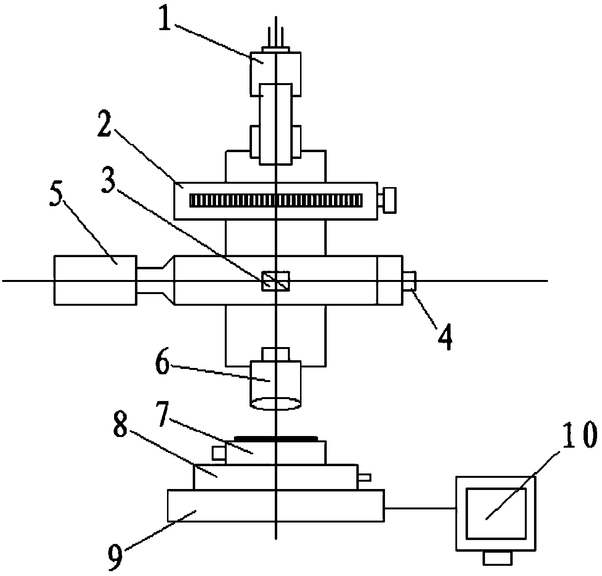
[0028] The invention uses image editing and design software such as L-EDIT and AUTOCAD to set the resolution of the graphics to be consistent with the minimum resolution of the digital micromirror device (DMD) or into an integer relationship, and the micro-optical element mask is first obtained on the digital lithography machine. Template (ie master). Such as figure 1 As shown, the light beam emitted by the violet light source 1 (high pressure mercury lamp) is expanded and collimated by the fiber point light source, and then directly irradiates the plug-in mask 2 (master), and the light beam transmitted by the prism beam splitter 4 , And then project the pattern on the mask plate on the photoresist-coated metal alloy substrate through the 10 times zoom objective lens 6, and the image of the pattern on the photoresist plate 7 in the substrate hold...
Embodiment 2
[0029] Embodiment 2, the process flow of making the metal alloy core of the diffractive micro-optical element
[0030] Grinding and polishing of metal alloy substrates—→substrate pretreatment (cleaning)—→photoresist homogenization—→pre-baking—→exposure—→post-baking—→development—→hard film—→electrochemical engraving of metal substrates Erosion—→Remove the glue—→Metal alloy core—→Injection mold assembly—→Injection molding machine—→Injection product (the micro-optical components remain on the optical plastic);
[0031] 1. Grinding and polishing of metal alloy substrate: The nickel-based metal alloy is wire-cut into the required wafer shape, the thickness of the substrate is about 3~5mm, if you want to make it into an injection mold core that can be used multiple times, the surface must be Only by grinding into a mirror can a high-quality finished product be produced;
[0032] Coarse grinding can be polished with metallographic sandpaper, and fine grinding is done by using existing equi...
Embodiment 3
[0049] Embodiment 3, injection molding manufacturing method of diffractive micro-optical element
[0050] The technology of replicating micro-optical elements containing surface diffractive microstructures is quite critical. It requires the existing replication technology to be able to replicate with high fidelity, and can make the diffraction efficiency and uniformity of the surface micro-optical element close to the value of the original microstructure (binary or multi-step structure). Injection molds are the main tool for the replication and molding of diffractive micro-optical elements. Generally speaking, these injection molded replicas are usually produced in batches. Therefore, plastic injection molds are required to have high efficiency, high quality and less processing or no processing after molding. Because of the characteristics of reprocessing (repair), the core material is high-temperature nickel-based metal alloy.
[0051] The design and production of the precision i...
PUM
 Abstract
Description
Claims
Application Information
 - R&D
- Intellectual Property
- Life Sciences
- Materials
- Tech Scout
- Unparalleled Data Quality
- Higher Quality Content
- 60% Fewer Hallucinations
Browse by: Latest US Patents, China's latest patents, Technical Efficacy Thesaurus, Application Domain, Technology Topic, Popular Technical Reports.
© 2025 PatSnap. All rights reserved.Legal|Privacy policy|Modern Slavery Act Transparency Statement|Sitemap|About US| Contact US: help@patsnap.com