Preparation method for silicon-carbon composite nano tube array

A nanotube array, silicon-carbon composite technology, applied in the field of lithium-ion batteries, can solve the problems of film and silicon cracking and pulverization, difficulty in large-scale production, poor cycle performance, etc., to achieve uniform size, controllable tube length, ratio of High volume effect

Inactive Publication Date: 2014-03-05
山东玉皇盛世化工股份有限公司
View PDF4 Cites 20 Cited by
  • Summary
  • Abstract
  • Description
  • Claims
  • Application Information

AI Technical Summary

Problems solved by technology

[0004] Cui et al. (M.-H.Park, M.G.Kim, J.Joo, K.Kim, J.Kim, S.Ahn, Y.Cui and J.Cho.Nano Lett. 2009, 9, 3844) used a porous anode Alumina templates are used to prepare silicon nanotubes as the negative electrode material of lithium-ion batteries, and the specific capacity of 2500mAh/g can still be maintained after 200 cycles; however, it is expensive, harsh conditions, poor reproducibility, and difficult to mass-produce
Chinese patent CN102983311A discloses the "preparation method of carbon nanotube-silicon composite negative electrode material". First, carbon nanotubes are prepared into carbon nanotube films, and then silane is decomposed in high-temperature gas phase to deposit a layer of silicon on the surface of carbon nanotube films; but its The thickness of the product is relatively thin, which requires pre

Method used


Image

  • Preparation method for silicon-carbon composite nano tube array
  • Preparation method for silicon-carbon composite nano tube array
  • Preparation method for silicon-carbon composite nano tube array

Examples


Embodiment 1

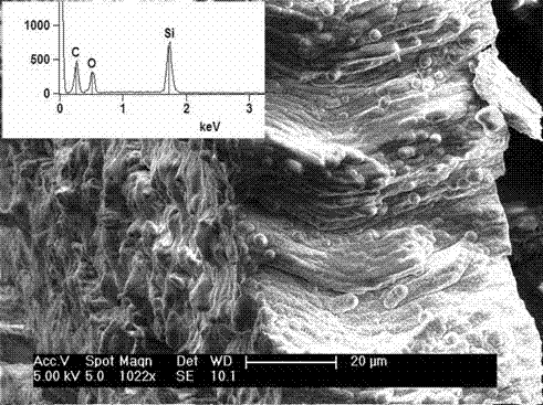
[0029] A porous anodized aluminum template with a pore size of 200 nm was placed in a corundum ark, placed in the heating zone of a tube furnace, and high-purity argon gas was passed through at a flow rate of 100 sccm for 2 hours, and the temperature was programmed to rise to 800 °C at 10 °C per minute. Acetylene gas with a flow rate of 50 sccm was injected for 30 minutes, and the temperature was naturally lowered after 2 hours of heat preservation. During this process, acetylene was decomposed in the high-temperature gas phase, and carbon atoms were deposited on the inner wall of the pores of the porous anodized aluminum template to obtain a carbon nanotube array contained in the template.

[0030] The carbon nanotube array was placed in the corundum ark, placed in the heating zone of the tube furnace, and vacuumed to 5 Pa and 10 Pa with a mechanical pump and a diffusion pump in turn. -2Pa, the temperature is programmed to rise to 700°C at 10°C per minute, the diffusion pump i...

Embodiment 2

[0035] Place a porous anodized aluminum template with a pore size of 200nm in a corundum ark, put it into the heating zone of a tube furnace, and pass argon gas at a flow rate of 100 sccm for 2 hours, then heat up to 700°C at a rate of 10°C per minute. 50 sccm of acetylene gas for 20 minutes, keep warm for 2 hours and then cool down naturally. During this process, acetylene is decomposed in high-temperature gas phase, and carbon atoms are deposited on the inner wall of the porous anodized aluminum template pores to obtain carbon nanotube arrays contained in the template.

[0036] The carbon nanotube array was placed in the corundum ark, placed in the heating zone of the tube furnace, and vacuumed to 5 Pa and 10 Pa with a mechanical pump and a diffusion pump in turn. -2 Pa, the temperature was programmed to rise to 700°C at 10°C per minute, the diffusion pump was stopped, 100sccm of argon gas was introduced, the position of the butterfly valve was adjusted, the system pressure w...

Embodiment 3

[0041] A porous anodized aluminum template with a pore size of 200nm was placed in a corundum ark, placed in the heating zone of a tube furnace, and nitrogen gas was passed through at a flow rate of 50 sccm for 2 hours, and then the temperature was programmed to rise to 600°C at 10°C per minute, and the flow rate was 20 sccm of acetylene gas for 30 minutes, keep warm for 2 hours and then cool down naturally. During this process, acetylene is decomposed in high-temperature gas phase, and carbon atoms are deposited on the inner wall of the porous anodized aluminum template pores to obtain a carbon nanotube array contained in the template.

[0042] The carbon nanotube array was placed in the corundum ark, placed in the heating zone of the tube furnace, and vacuumed to 5 Pa and 10 Pa with a mechanical pump and a diffusion pump in turn. -2 Pa, the temperature was programmed to rise to 600°C at 10°C per minute, the diffusion pump was stopped, nitrogen gas of 100 sccm was introduced, ...


PUM

PropertyMeasurementUnit
Apertureaaaaaaaaaa

Abstract

The invention belongs to the field of lithium ion batteries and discloses a preparation method for a silicon-carbon composite nano tube array. The preparation method for the silicon-carbon composite nano tube array is characterized by comprising the following steps: raising the temperature of a porous-anode aluminum oxide template under inert gas; introducing acetylene gas; generating a carbon nano tube array on the surface of the template by high-temperature gas-phase decomposition of acetylene; vacuumizing and introducing the inert gas, hydrogen and silane after the temperature is raised; decomposing silane to obtain a coaxial carbon nano tube and silicon nano tube array in the template; and removing silicon oxide on the surface of the template by using a hydrofluoric acid aqueous solution and drying to obtain the silicon-carbon composite nano tube array. According to the preparation method for the silicon-carbon composite nano tube array, the silicon-carbon composite nano tube array with controllable pipe diameter, pipe length and wall thickness, and uniform size can be obtained by two-step chemical vapor deposition and hydrofluoric acid corrosion; in a whole production process, complicated equipment is not used and process steps are simple, so that large-scale industrial production is facilitated; the stability of the silicon-carbon composite nano tube array is good.

Description

(1) Technical field [0001] The invention belongs to the field of lithium ion batteries, in particular to a method for preparing a silicon-carbon composite nanotube array. (2) Background technology [0002] Lithium-ion batteries have played an important role in our lives thanks to their long cycle life and high specific capacity since they were invented; especially with the intensification of energy shortages and the deepening of people's use of new energy, we are increasingly The more energy storage devices that can be charged and discharged on a large scale are needed, the lithium-ion battery has become the preferred energy storage device due to its mature technology and excellent performance in all aspects. However, as an energy storage device, the specific capacity of lithium-ion batteries is not large enough, so how to effectively improve the specific capacity of lithium-ion batteries is the main scientific research goal at this stage. Silicon atoms can combine up t...

Claims


Application Information

Patent Timeline
IPC IPC(8): H01M4/38B82Y40/00
CPCB82Y40/00H01M4/366H01M4/386H01M4/587H01M10/0525Y02E60/10
Inventor 赵成龙宋春华王瑛陈欣
Owner 山东玉皇盛世化工股份有限公司
Why Eureka
Try Eureka