Low temperature organic malodorous gas treating system

A malodorous gas and treatment system technology, which is applied to the treatment of organic malodorous gas with a temperature lower than 5°C, and the field of low-temperature organic malodorous gas treatment system, can solve the problems of low malodorous gas treatment efficiency, environmental hazards, endocrine disorders, etc., and achieves elimination of unfavorable Influence, system structure is simple, the effect of guaranteeing the processing effect

Active Publication Date: 2014-03-12
NISHIHARA ENVIRONMENT ENG SHANGHAI CO LTD
View PDF2 Cites 11 Cited by
  • Summary
  • Abstract
  • Description
  • Claims
  • Application Information

AI Technical Summary

Problems solved by technology

[0003] In addition, the odor produced by some chemical factories, pharmaceutical factories, printing and dyeing factories and other production workshops and their sewage treatment facilities may contain a large amount of difficult-to- Biochemically degraded organic compounds, such as polycyclic aromatic hydrocarbons, heterocyclic compounds, chlorinated aromatic compounds, organic cyanides, organic synthetic polymer compounds, etc. The harm of these organic compounds to the environment is mainly reflected in: (1) long-term Residuality: Once discharged into the environment, they are difficult to be decomposed; (2) Bioaccumulation; the concentration in the organism after being enriched by the biological food chain is much higher than the concentration in the surrounding environment; (3) Semi-volatile: Volatile in the air (4) High toxicit

Method used


Image

  • Low temperature organic malodorous gas treating system
  • Low temperature organic malodorous gas treating system

Examples


Embodiment Construction

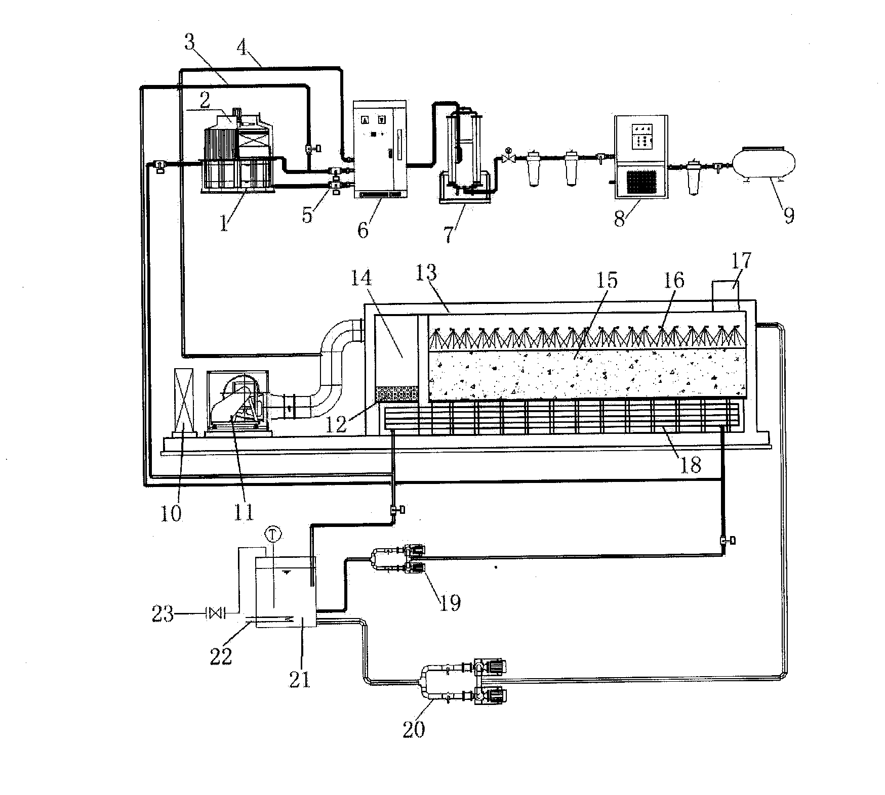
[0060] In the figure: 1. Cooling pool, 2. Cooling tower, 3. Ozone generator cooling water outlet pipe, 4. Ozone gas outlet pipe, 5. Ozone generator cooling water inlet valve, 6. Ozone generator, 7. Oxygen production Machine, 8. Cold dryer, 9. Air compressor, 10. Control cabinet, 11. Fan, 12. Ozone destruction catalyst layer, 13. Biological deodorization tower, 14. Ozone oxidation pre-reaction area, 15. Carbonaceous organisms Media filler, 16. Spray nozzle, 17. Air outlet, 18. Waste heat recovery device, 19. Heating circulating water pump, 20. Spray water pump, 21. Spray water tank, 22. Heating device, 23. Reclaimed water or tap water pipeline .

[0061] The specific implementation manner of the present invention will be described below in conjunction with the accompanying drawings.

[0062] from figure 1 It can be seen that the low-temperature organic malodorous gas treatment system is composed of an odor collection system, an ozone generation system, an ozonation pre-reacti...


PUM

PropertyMeasurementUnit
Apertureaaaaaaaaaa
The average particle sizeaaaaaaaaaa
Filling densityaaaaaaaaaa

Abstract

The invention discloses a low temperature organic malodorous gas treating system, comprising a malodorous gas collection system, an ozone generation system, an ozonation pre-reaction zone, a biological deodorizing tower, a heat energy recovery system and a spraying and watering device. During operation of the treating system, organic malodorous gas having passed through a deodorizing fan is mixed with ozone from an ozone generator in a conveying pipeline, a gas mixture enters into the ozonation pre-reaction zone, gas obtained after completion of a reaction enters into the biological deodorizing tower through the bottom of the biological deodorizing tower, and the heat energy recovery system is arranged at the bottom of the biological deodorizing tower. In the biological deodorizing tower, pollutants in malodorous gas is decomposed by microbes in a carbonaceous biological filter pack and then discharged from an air outlet at the upper part of the biological deodorizing tower after reaching standards, and the spraying and watering device is arranged above the filter pack. The low temperature organic malodorous gas treating system provided by the invention is especially applicable to treatment of organic malodorous gas at a temperature of less than 5 DEG C and has the advantages of a simple structure, basically no generation of secondary pollution, low operation cost and simple operation and management.

Description

technical field [0001] The invention relates to a polluted air treatment technology, in particular to a low-temperature organic malodorous gas treatment system, especially suitable for the treatment of organic malodorous gases with a temperature lower than 5°C. Background technique [0002] The main odor generated by the influent lifting pump room of the municipal sewage treatment plant is hydrogen sulfide. The odor generated during the anaerobic digestion of the sludge in the primary sedimentation tank is mainly hydrogen sulfide and other sulfur-containing gases. Ammonia gas and other volatile substances may be produced. Ammonia, amines, sulfides, fatty acids, aromatics and dimethyl sulfide will be produced during the composting process. The process of aerobic digestion and sludge air drying may produce a small amount of hydrogen sulfide, but mainly mercaptan and dimethyl sulfide gas. These substances can be removed by biodegradation. [0003] In addition, the odor prod...

Claims


Application Information

Patent Timeline
IPC IPC(8): B01D53/75B01D53/76B01D53/85B01D53/52B01D53/72B01D53/48B01D53/58B01D53/54
CPCY02A50/20
Inventor 长英夫鞠庆玲
Owner NISHIHARA ENVIRONMENT ENG SHANGHAI CO LTD
Why Eureka
Try Eureka