

Microemulsion metal cutting fluid
A metal cutting fluid and microemulsion technology, applied in the petroleum industry, lubricating compositions, etc., can solve the problems of high cost, environmental pollution, etc., and achieve the effects of long working life, good chip removal, and lubricating performance
- Summary
- Abstract
- Description
- Claims
- Application Information
AI Technical Summary
Problems solved by technology
Method used
Image

Examples
Embodiment 1
[0055] The raw material formula is shown in Table 1;
[0056] Preparation:
[0057] Add fatty oil, emulsifier and co-emulsion agent into the reaction kettle in proportion, and stir evenly; mix the anti-wear and rust inhibitor, pH regulator and penetrating agent evenly in proportion, then add to the reaction kettle, heat up to 70-80°C, and stir Until a transparent and clear homogeneous liquid is formed; cool down to 30°C, add an appropriate amount of defoamer and anti-corrosion and antibacterial agent, stir evenly, and the obtained concentrated stock solution of cutting fluid is obtained.
[0058] Table 1 Microemulsion metal cutting fluid formula (mass fraction)
[0059]
[0060]
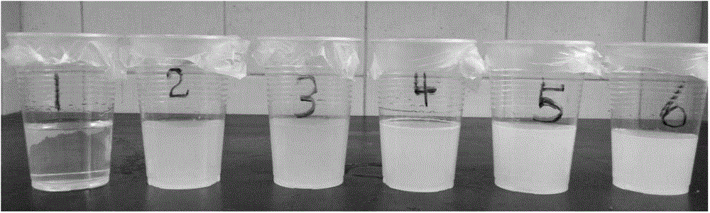
[0061] The concentrated stock solutions of microemulsion metal cutting fluids exemplified in Table 1 are all transparent and uniform brownish-yellow clear solutions, without layered phase transition and gel-like appearance, and have good storage stability. The working solution diluted 20 time...
Embodiment 2
[0063] Raw material formula composition: 100g olive oil, 25g Span 80, 225g Tween 80, 100g ethylene glycol, 150g AEO9, 150g lauric acid diethanolamide borate, 50g benzotriazole, 50g isooctyl phosphate, 10g aminomethylpropanol, 90g triethanolamine, 40g higher alcohol fatty acid ester complex defoamer and 10g methylene bismorpholine antiseptic antibacterial agent;
[0064] The preparation method of lauric acid diethanolamide borate: add lauric acid and diethanolamine at a molar ratio of 1:1 to a four-necked bottle with a stirrer, a condenser, and a thermometer, control the reaction temperature at 120-170°C, and stir for 2 ~4h for amidation reaction, using benzene as water-carrying agent to carry out vacuum distillation to remove water to obtain lauric acid diethanolamide; in a four-necked bottle with reflux condenser, oil-water separator, constant pressure dropping funnel and thermometer , respectively add lauric acid diethanolamide and boric acid at a molar ratio of 1:1 (boric a...
Embodiment 3
[0067] Raw material formula composition: 100g olive oil, 25g Span 80, 225g Tween 80, 100g ethylene glycol, 150g AEO9, 150g oleic acid diethanolamide borate, 50g benzotriazole, 50g isooctyl phosphate, 10g aminomethylpropanol, 90g triethanolamine, 40g higher alcohol fatty acid ester complex defoamer and 10g methylene bismorpholine antiseptic antibacterial agent;
[0068] The preparation method of oleic acid diethanolamide borate: add oleic acid and diethanolamine in a molar ratio of 1:1 into a four-necked bottle with a stirrer, condenser and thermometer, control the reaction temperature at 120-170°C, stir for 2 ~4h for amidation reaction, using benzene as water-carrying agent to carry out vacuum distillation to remove water to obtain oleic acid diethanolamide; in a four-necked bottle with reflux condenser, oil-water separator, constant pressure dropping funnel and thermometer , respectively add oleic acid diethanolamide and boric acid at a molar ratio of 1:1 (boric acid is groun...
PUM
| Property | Measurement | Unit |
|---|---|---|
| Particle size | aaaaa | aaaaa |
Abstract
Description
Claims
Application Information