Industrial organic waste gas treatment and cleaning process

A technology of organic waste gas and organic gas, which is applied in the field of activated carbon steam desorption cleaning process, can solve the problems of increasing the load of the adsorption tower and heating air energy consumption, unused latent heat of steam, and increasing the load of the adsorption tower, etc., to meet the requirements of clean production , Improve the efficiency of oil-water separation and reduce the solubility

Inactive Publication Date: 2015-03-25
LANZHOU INST OF CHEM PHYSICS CHINESE ACAD OF SCI +1
View PDF7 Cites 9 Cited by
  • Summary
  • Abstract
  • Description
  • Claims
  • Application Information

AI Technical Summary

Problems solved by technology

Activated carbon water vapor desorption process, due to the advantages of simple process, wide application range, safe operation, and low equipment investment by 1 / 2~1 / 3, has the earliest industrial application time and mature process equipment, but it has low heat energy utilization rate and waste water discharge. Secondary pollution, etc.
[0005] Aiming at the activated carbon steam desorption process, Sun Zongchang et al. (Chinese patent ZL 200910065213.1) invented a method for recovering ethyl acetate in the steam desorption condensed wastewater through the aeration tower, but the load of the adsorption tower and the energy consumption of heating air were increased, and the desorption was limited. With the impact of ethyl acetate hydrolysis and solubility balance, it is still necessary to discharge waste water containing organic matter; Cai Zhihuang (Chinese patent ZL 200610037129.5) invented a method of using the waste heat of desorbed water vapor to heat waste water to recover solvent through partition heat exchange, but most of the steam The latent heat is not used, and the load of the adsorption tower is increased and the wastewater containing organic matter still needs to be discharged

Method used


Image

  • Industrial organic waste gas treatment and cleaning process
  • Industrial organic waste gas treatment and cleaning process
  • Industrial organic waste gas treatment and cleaning process

Examples


Embodiment 1

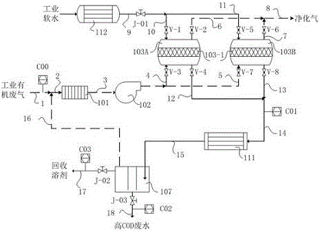
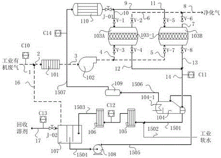
[0077] The source, composition and process parameters of industrial organic waste gas are the same as in Comparative Example 1, and its flow rate and stream composition are shown in Table 11-1C10. Adopt cleaning process of the present invention to handle (see figure 2), the organic waste gas from the main pipe 1 and the non-condensable gas from the discharge pipeline 16 of the oil-water separator (107) is mixed in the pipeline 2, connected to the surface cooler (101) for cooling, cooled to below 40°C, filtered, and blown by the fan (102) Boost the pressure and send it to the adsorption tower A (103A). The VOCs in the gas are adsorbed and purified by the activated carbon layer (103-1). The designed adsorption efficiency is not less than 98%, and the purified gas is discharged up to the standard. Each adsorption tower is filled with columnar granular activated carbon, and is equipped with a water cooling coil to remove the heat of adsorption, prevent the activated carbon layer ...

Embodiment 2

[0087] The source, composition and process parameters of industrial organic waste gas are the same as in Comparative Example 2, and its flow rate and stream composition are shown in Table 12-1C10. Adopt cleaning process of the present invention to handle (see figure 2 ), the specific process and operation are the same as in Example 1.

[0088] Table 12-1 Simulation calculation results of electrostatic spray painting organic waste gas cleaning treatment process in machinery industry#

[0089]

[0090] #: The desorption solvent recovery rate of the cleaning process (%) = the sum of the organic matter flow rate of "C11" × 100 / the sum of the organic matter flow rate of "C13", and the calculation result is 84.75%.

Embodiment 3

[0095] The source, composition and process parameters of industrial organic waste gas are the same as in Comparative Example 3, and the flow rate and stream composition are shown in Table 13-1C10. Adopt cleaning process of the present invention to handle (see figure 2 ), except that the adsorption tower is filled with honeycomb activated carbon, other specific processes and operations are the same as in Example 1.

[0096] Table 13-1 Simulation calculation results of organic waste gas cleaning treatment process from semiconductor integrated circuit production#

[0097]

[0098] #: The desorption solvent recovery rate of the cleaning process (%) = the sum of the organic matter flow rate of "C11" × 100 / the sum of the organic matter flow rate of "C13", and the calculation result is 92.83%.

[0099] Compared with Comparative Example 3, the heat used for desorption steam heating is reduced from 3857 kcal / hour to 403 kcal / hour, saving energy consumption by 89.25% (calculation m...


PUM


Abstract

The invention discloses an industrial organic waste gas treatment and cleaning process. The process includes adsorption, desorption and steam desorption treatment. The desorption steam flow as a heating medium forms a condensate through a jacket or coil of an evaporator; the condensate is mixed with supplemented industrial soft water and further cooled through a cooler one and a cooler two; and the mixture is discharged into an oil-water separator. Gaseous organic compounds and non-condensable gas merge into the industrial organic waste gas for treatment; liquid organic matters close to the equilibrium solubility and water are subjected to standing and stratification; an upper organic phase layer is recovered as a mixed organic solvent; a lower layer of steam condensate water as the circulating water is pressurized by a cold water pump and sent into the evaporator for evaporation; the generated circulating steam is sent to a steam drum for buffer, and then is subjected to temperature and pressure adjustment by a steam superheater, so that the circulating steam can substitute industrial steam in the desorption process of activated carbon. The invention realizes cycle utilization of desorption steam condensate, has no waste water discharge, at the same time improves the utilization rate of heat energy, and meets the requirements of energy saving, emission reduction and clean production.

Description

technical field [0001] The invention relates to an activated carbon vapor desorption cleaning process for industrial organic waste gas treatment, and belongs to the technical field of environmental protection and air pollution control. Background technique [0002] Most of the volatile organic pollutants (Volatile Organic Compounds, VOCs) are toxic, harmful, and have certain carcinogenicity; participate in photochemical reactions, form photochemical smog, or produce secondary organic aerosols, causing large areas of urban air "smog"; Partially depletes the ozone layer. Industries involving VOCs emissions, including petrochemicals, fine chemicals, spraying, packaging and printing, pharmaceutical and pesticide manufacturing, semiconductor and electronic product manufacturing, wood-based panels and wooden furniture manufacturing, leather, enameled wire, shoemaking, coatings, inks, adhesives Mixture production, metal casting, etc., there are many industries, and the VOCs produc...

Claims


Application Information

Patent Timeline
Patent Type & Authority Applications(China)
IPC IPC(8): B01D53/04
Inventor 陈革新方荣刚王金梅刘文清赵培庆黄三明姚彩兰李康飞苟明霞方敬文
Owner LANZHOU INST OF CHEM PHYSICS CHINESE ACAD OF SCI
Why Eureka
Try Eureka