
Sulfur doped graphite phase carbon nitride pholocatalyst and application thereof in photocatalysis TCP (2,4,6-trichlorophenol) degradation reaction and photocatalysis hydrogen preparation reaction

A phase carbon nitride photocatalyst technology, applied in physical/chemical process catalysts, hydrogen production, chemical instruments and methods, etc., can solve the problems of low electron-hole separation efficiency and limited value, and achieve strong visible light absorption. ability, high electron-hole separation efficiency, high activity effect

Inactive Publication Date: 2015-06-24
LIAONING UNIVERSITY OF PETROLEUM AND CHEMICAL TECHNOLOGY
View PDF4 Cites 29 Cited by
  • Summary
  • Abstract
  • Description
  • Claims
  • Application Information

AI Technical Summary

Problems solved by technology

Although g-C3N4 has a moderate energy band and can directly utilize visible light, its electron-hole separation efficiency is still low, which greatly limits its practical value. [Nat. Mater. 2009, 8, 76-80]

Method used


Image

  • Sulfur doped graphite phase carbon nitride pholocatalyst and application thereof in photocatalysis TCP (2,4,6-trichlorophenol) degradation reaction and photocatalysis hydrogen preparation reaction
  • Sulfur doped graphite phase carbon nitride pholocatalyst and application thereof in photocatalysis TCP (2,4,6-trichlorophenol) degradation reaction and photocatalysis hydrogen preparation reaction
  • Sulfur doped graphite phase carbon nitride pholocatalyst and application thereof in photocatalysis TCP (2,4,6-trichlorophenol) degradation reaction and photocatalysis hydrogen preparation reaction

Examples


Embodiment 1

[0029] A step: put 5 g of melamine into the crucible 520 o C roasting 2 h, the heating rate is 5 o C / min, air atmosphere, cooled to room temperature, to obtain graphitic carbon nitride (g-C 3 N 4 )catalyst.

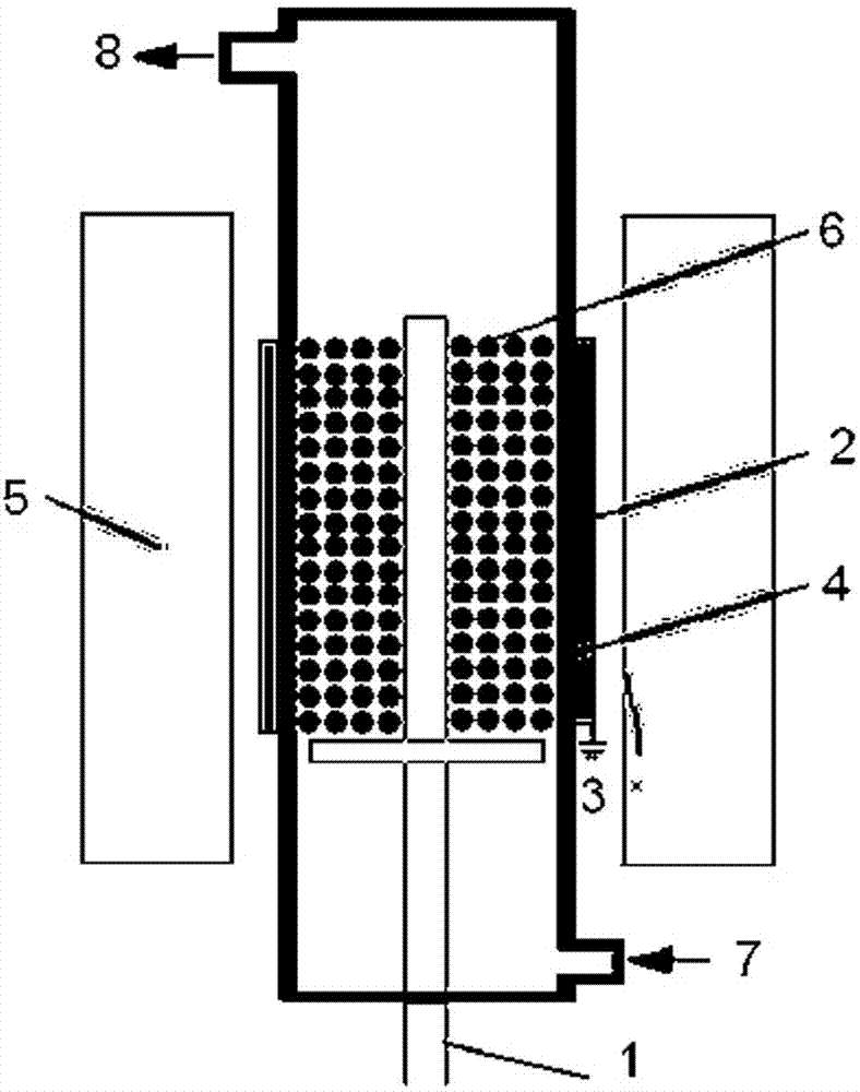
[0030] Step B: with H 2 S is the discharge gas, and a dielectric barrier discharge plasma generator is used to pair g-C 3 N 4 The catalyst is subjected to discharge treatment. The dielectric barrier discharge plasma generator consists of a quartz tube and two electrodes. A stainless steel wire with a diameter of 2.5 mm is used as a high-voltage electrode, which is installed at the axis of the quartz tube, and one end is connected to an AC power supply. The aluminum foil tightly wound outside the quartz tube is used as the ground electrode and connected to the ground. The structure diagram of the dielectric barrier discharge plasma generator is as follows: figure 1 Shown or use the existing commercially available plasma generator. see figure 1As shown, 1 is the ...

Embodiment 2

[0032] A step in embodiment 1.

Embodiment 3

[0034] Change the discharge time of step B in Example 1 to 10 min, and keep other steps and conditions unchanged.


PUM

PropertyMeasurementUnit
Diameteraaaaaaaaaa

Abstract

The invention belongs to the technical field of semiconductor photocatalysis, and in particular relates to a sulfur doped graphite phase carbon nitride pholocatalyst and application thereof in photocatalysis TCP (2,4,6-trichlorophenol) degradation reaction and photocatalysis hydrogen preparation reaction. A dielectric barrier discharge plasma generator is adopted, and H2S is used as a discharge gas to perform discharge treatment on a graphite phase carbon nitride catalyst. The sulfur species have high activity under a plasma state, so that compared with a conventional preparation method, graphite phase carbon nitride catalysts can be doped more easily. The sulfur doped graphite phase carbon nitride pholocatalyst provided by the invention has the advantages that the sulfur doped amount is adjustable, the specific area of a product catalyst is large, the visible light absorbability is strong, the electron-hole separation efficiency is high, and the photocatalysis performance is good. The catalyst prepared by the method provided by the invention is applied to a photocatalysis degradation process of a common pollutant namely 2,4,6-trichlorophenol (TCP) and a photocatalysis water decomposition hydrogen preparation process, the same evaluation device is adopted, and compared with the sulfur doped graphite phase carbon nitride pholocatalyst prepared by a conventional method, the sulfur doped graphite phase carbon nitride pholocatalyst provided by the invention shows more superior catalytic activity.

Description

technical field [0001] The invention belongs to the technical field of semiconductor photocatalysis, and in particular relates to a sulfur-doped graphite phase carbon nitride photocatalyst and its application in photocatalytic degradation of TCP reaction and photocatalytic hydrogen production reaction. Background technique [0002] With the increasingly serious problems of environmental pollution and energy crisis in recent years, solar energy, hydrogen energy, etc. as clean energy are gradually replacing traditional fossil energy on the stage of history. Semiconductor materials as photocatalysts have attracted the attention of many scholars in the fields of physics, chemistry, environmental protection, and materials. The current semiconductor photocatalysts are mostly metal oxides and sulfides. When a semiconductor photocatalyst is exposed to light, the electrons in the valence band absorb light energy and jump to the conduction band, which makes the catalyst generate a la...

Claims


Application Information

Patent Timeline
IPC IPC(8): B01J27/24A62D3/17C01B3/04A62D101/28
CPCY02E60/36
Inventor 胡绍争李法云范志平王菲
Owner LIAONING UNIVERSITY OF PETROLEUM AND CHEMICAL TECHNOLOGY
Learn More