
Engine tail gas cleanup device

A technology for exhaust gas purification devices and engines, which is applied to exhaust devices, engine components, machines/engines, etc., can solve the problems of easy volatilization of materials, slow start-up, and difficult preparation, and achieve the requirements of reducing materials and manufacturing processes, reducing Costs and Procedures, Effects of Improving Catalytic Efficiency

Active Publication Date: 2015-09-23
黄石
View PDF5 Cites 12 Cited by
  • Summary
  • Abstract
  • Description
  • Claims
  • Application Information

AI Technical Summary

Problems solved by technology

Among them, RuO 2 When used as an electrode, the current efficiency is the highest at 12%, but this material is volatile and highly toxic, which inhibits its application prospects
[0006] Using SOFC for nitrogen oxide reduction on the basis of ECC can obtain additional electric energy and improve the energy utilization rate. However, traditional SOFC requires a dense electrolyte layer, which is difficult to prepare, requires high airtightness of the battery, and requires additional sealing. Materials, poor thermal shock resistance, slow startup, can not meet the needs of automobile exhaust treatment

Method used


Image

  • Engine tail gas cleanup device
  • Engine tail gas cleanup device

Examples


preparation example Construction

[0039] Correspondingly, a method for preparing a single solid oxide fuel cell with a support, the steps are:

[0040]1) According to the chemical composition of the perovskite-type catalyst, take the nitrate of the corresponding metal ion, make it into a gel, dry it, and grind it to obtain the catalyst powder;

[0041] 2) Mix the catalyst powder, PSZ powder, and organic solvent prepared in the previous step to make a spinning solution, and obtain a hollow fiber green body through a spinning machine, cut into sections, and then calcined to make a porous hollow fiber support;

[0042] 3) Dissolving the cermet powder in an organic solvent, coating it on the support, and calcining it to obtain the anode layer;

[0043] 4) The electrolyte material is dissolved in an organic solvent, coated on one end of the surface of the anode layer, and one end is set aside, and calcined to obtain the electrolyte layer; the electrolyte material is ZrO 2 Base electrolyte material, CeO 2 Base ele...

Embodiment 1

[0053] In this embodiment, the battery anode material is Ni-YSZ powder, and the battery cathode material uses perovskite catalyst powder La 0.6 Sr 0.4 co 0.2 Fe 0.8 o 3-δ , with La (NO 3 ) 3 ·6H 2 O, Sr(NO 3 ) 2 , Co(NO 3 ) 2 ·6H 2 O and Fe(NO 3 ) 3 9H 2 O is prepared by the sol-gel method. Specifically, weigh the nitrate with a molar ratio of lanthanum, strontium, cobalt, and iron of 3:2:1:4, dissolve it in deionized water, and stir it in a constant temperature water bath at 80°C to form a nitrate solution. , adding citric acid monohydrate with a molar ratio of 2:1 to the metal ion, and then adding polyethylene glycol with a molar ratio of 6:1 to the metal ion to the solution, stirring in a constant temperature water bath at 80°C for 2 hours to form a metal ion chelating solution, Then put the chelating solution into a constant temperature drying oven at 200°C for high temperature drying for 12 hours to form a gel. Then the gel was put into a muffle furnace, ca...

Embodiment 2

[0058] The difference between this embodiment and the first embodiment is that the cathode powder La in the first embodiment 0.6 Sr 0.4 co 0.2 Fe 0.8 o 3-δ Change to La 0.6 Sr 0.4 co 0.2 Fe 0.4 Cu 0.4 o 3-δ , other conditions are the same as those in Embodiment 1.


PUM


Abstract

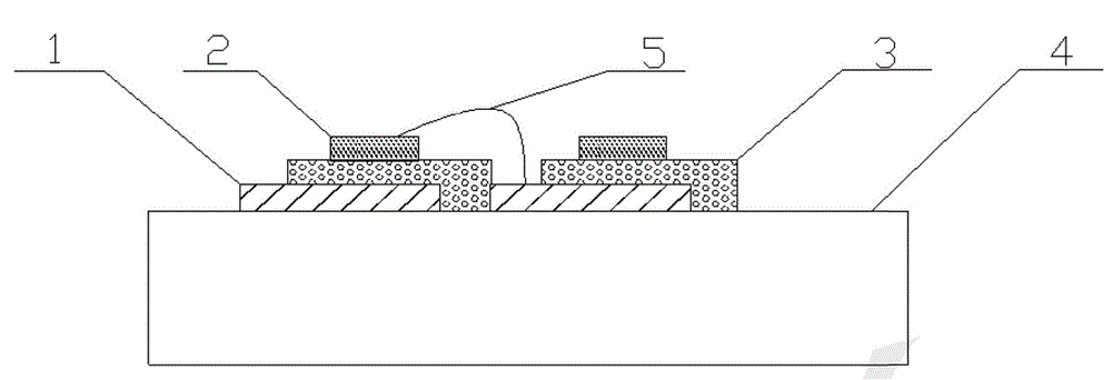
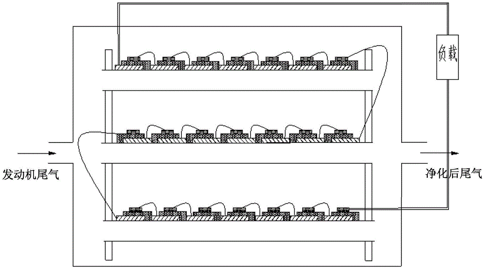
The invention discloses an engine tail gas cleanup device. A solid oxide fuel mono-cell with a supporting body comprises the supporting body and a mono-cell unit arranged on the supporting body. The mono-cell unit comprises an anode layer, a cathode layer and an electrolyte layer; one end of the anode layer is coated by the electrolyte layer; the cathode layer is arranged on the other side surface of the electrolyte layer opposite to the coating layer. A solid oxide fuel cell pack with the supporting body comprises the supporting body and a plurality of mono-cell units which are connected in series, and the anode layers of the mono-cell units are closely connected with the supporting body. The engine tail gas cleanup device comprises a plurality of solid oxide fuel cell packs with supporting bodies. A preparation method of the solid oxide fuel mono-cell comprises the steps as follows: preparing a catalyst powder; preparing the porous hollow fiber supporting body; preparing the anode layer; preparing the electrolyte layer and preparing the cathode layer. The cleanup device of the invention could generate electric energy while purifying tail gas.

Description

technical field [0001] The invention relates to an engine tail gas purification device. Background technique [0002] The main pollutants of automobile exhaust are carbon monoxide (CO), hydrocarbons (HCs), nitrogen oxides (NO x ) and suspended particles. At present, the most commonly used exhaust gas catalytic technology is the Pt-Pd-Rh three-way catalytic system, in which Pt and Pd play a major role in the catalytic oxidation of CO, while Rh has a good activation effect on the dissociation of NO. [0003] However, since Pt, Pd, and Rh are all scarce precious metals with few reserves and high prices, one of the current research trends of three-way catalysts is to replace Pt and Rh with relatively cheap Pd, and add rare earth additives to improve catalytic performance. On the other hand, the use of base metals, rare earth oxides and other materials to replace noble metals to prepare three-way catalysts has also been widely studied, and some progress has been made. [0004]...

Claims


Application Information

Patent Timeline
Patent Type & Authority Applications(China)
IPC IPC(8): H01M8/12B01D53/92F01N3/20
CPCB01D53/925F01N3/108F01N3/20H01M8/1226H01M8/1286H01M2008/1293H01M2250/20Y02E60/50
Inventor 张覃
Owner 黄石
Learn More