
Flexible cadmium telluride solar cell with graphene insertion layer

A technology of solar cells and insertion layers, applied in circuits, photovoltaic power generation, electrical components, etc., can solve problems such as unsatisfactory effect, thickness affecting battery electrical connection, device performance degradation stability, etc.

Active Publication Date: 2016-02-24
SICHUAN UNIV
View PDF4 Cites 2 Cited by
  • Summary
  • Abstract
  • Description
  • Claims
  • Application Information

AI Technical Summary

Problems solved by technology

For the former, due to the high resistivity, its thickness greatly affects the electrical connection of the battery; for the latter, the high resistivity of MoOx and the rapid diffusion of Cu often cause the degradation of device performance and stability problems
There are also ZnTe or Au / Pd as the insertion layer, but the effect is not ideal, and the rectification effect can still be observed, which may be related to the subsequent high-temperature deposition or treatment process of the insertion layer

Method used


Image

  • Flexible cadmium telluride solar cell with graphene insertion layer
  • Flexible cadmium telluride solar cell with graphene insertion layer

Examples


Embodiment 1

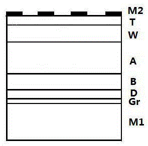
[0021] I. First, deposit graphene (Gr) by CVD method, put Ni foil (M1) into the vacuum chamber, and evacuate to about 2×10 4 Pa, the substrate temperature is 900 0 C~1000 0 C, introduce argon gas mixed with 5% methane, the gas flow rate is 50 sccm, hydrogen gas is 500 sccm, the deposition time is about 50-120 s, and the cooling process is passed through 2000 sccm argon gas and 500 sccm hydrogen gas.

[0022] II. Next, deposit about 1 nm of Bi (D) and about 50 nm of Te (B) by evaporation.

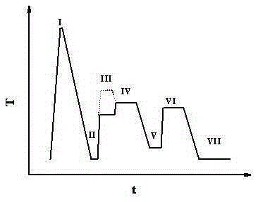
[0023] III~IV. Subsequently, as attached figure 2 As shown by the solid line in process III, cadmium telluride (A) is prepared by evaporation method with a thickness of about 5000 nm, and the substrate temperature is 350 0 C, followed by evaporation of 400nm CdCl 2 , then annealed in air at 440 0 c.

[0024] V~VI. The deposition of cadmium sulfide (W) adopts the chemical water bath method, and the drugs used are all analytical reagents, prepared with secondary deionized water, and the...

Embodiment 2

[0027] I. Deposit graphene (Gr) by VD method, put Ni foil (M1) into the vacuum chamber, and evacuate to about 2×10 4 Pa, the substrate temperature is 900 0 C~1000 0 C, introduce argon gas mixed with 5% methane, the gas flow rate is 50 sccm, hydrogen gas is 500 sccm, the deposition time is about 50-120 s, and the cooling process is passed through 2000 sccm argon gas and 500 sccm hydrogen gas.

[0028] II. Next, deposit about 1 nm of Sb (D) and about 50 nm of Te (B) by evaporation.

[0029] III~IV. Subsequently, as attached figure 2 As shown by the dotted line in Process III, Cd(A) is prepared by the near-space sublimation method with a thickness of about 6000 nm and a deposition temperature of about 570 0 C, followed by evaporation of 400nm CdCl 2 , then annealed in air at 440 0 c.

[0030] V~VI. Deposition of cadmium sulfide (W) by sputtering method to deposit about 50nm, of which the purity of CdS target is 99.99%, and the background vacuum is ~10 -4 Pa, the working g...


PUM


Abstract

The invention discloses a flexible cadmium telluride solar cell with a graphene insertion layer. With nickel foil as a substrate and graphene as the insertion layer, the nickel foil and the graphene are arranged on the substrate; and a doped layer and a barrier layer are fabricated behind the insertion layer to form a back contact layer of the flexible cadmium telluride solar cell. Meanwhile, a ZnO-based transparent conductive composite thin film is adopted by a front contact layer; and a copper-free structural design and a copper-free technological treatment process are adopted by the solar cell, so that the photoelectric conversion efficiency of the flexible solar cell can be greatly improved; the long-term stability of a device is improved; and the structural design of the device and the selection of the back contact layer are well compatible to the technological process. In addition, due to the self-support characteristics of the graphene insertion layer, the graphene can be stripped from the metal substrate as an independent transparent cell, and can also be transplanted to a bottom cell to fabricate an efficient laminated cell.

Description

technical field [0001] The invention belongs to the field of new energy materials and devices. Background technique [0002] For more than ten years, many countries in the world are actively developing thin-film solar cells: amorphous silicon solar cells, copper indium (gallium) selenium solar cells, and cadmium telluride solar cells. Compared with crystalline silicon solar cells, it has potential advantages in production and other aspects. Usually the functional layer of thin-film solar cells is only a few microns thick, but glass substrates with a thickness of 1-4 mm are often used. In this way, about 98% of the weight of the entire battery is concentrated on the substrate. If other light-weight substrates are used instead of glass, devices with high specific power (the ratio of output power to device weight) can be obtained. [0003] In terms of space exploration, the most basic requirement for space power is high specific power, which is conducive to the low-cost launc...

Claims


Application Information

Patent Timeline
Patent Type & Authority Applications(China)
IPC IPC(8): H01L31/0224
CPCH01L31/022425H01L31/022466Y02E10/50
Inventor 李卫唐楠武莉莉张静全冯良桓黎兵刘才曾广根王文武
Owner SICHUAN UNIV
Learn More