
High-capacity lithium ion battery negative electrode plate and preparation method thereof

A technology for lithium-ion batteries and negative pole pieces, which is applied in the direction of electrode manufacturing, battery electrodes, and secondary batteries. Effects of cycle performance, improvement of electronic conductivity, and improvement of safety performance

Inactive Publication Date: 2017-02-01
XIAMEN RIZHEN POWER TECH CO LTD
View PDF4 Cites 21 Cited by
  • Summary
  • Abstract
  • Description
  • Claims
  • Application Information

AI Technical Summary

Problems solved by technology

However, they are accompanied by significant volume changes (increase of about 300%) during their use, resulting in pulverization and deactivation of electrode materials, resulting in rapid capacity decay, and have not been practically applied to commercial products.
The methods for making the silicon base mainly include: 1) nanometerization of materials, but the improvement is not large, and the expansion rate is still relatively large; 2) doping modification, but the effect is not obvious, such as patent CN103346305A discloses the following: Nano-silicon and artificial graphite are dissolved in the dispersant to obtain a uniform dispersion, and then an organic carbon source is added for coating, and finally a silicon-carbon composite negative electrode material for lithium batteries with artificial graphite as the carrier is obtained. Although the prepared material has an improved gram capacity , but its initial efficiency is low and cycle performance is poor
3) The silicon material is deposited on the surface of the current collector to prepare a silicon-based current collector. However, during the charging and discharging process, the expansion problem between the silicon material and the current collector has not been solved, and the effect is not obvious.
For example, the patent (CN100555733C) discloses an invention patent battery, which mainly adopts the deposition of silicon compound or silicon material on the surface of the current collector. Although the discharge capacity is improved, the cycle performance is poor. On the one hand, the expansion of silicon is controlled due to the charging and discharging process. , but the improvement range is limited. On the other hand, the deviation of the conductivity of the silicon material causes its rate and cycle performance to be low, making it difficult to promote industrialization.

Method used

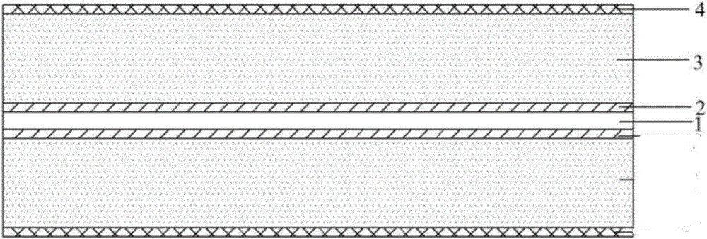

Image

  • High-capacity lithium ion battery negative electrode plate and preparation method thereof
  • High-capacity lithium ion battery negative electrode plate and preparation method thereof
  • High-capacity lithium ion battery negative electrode plate and preparation method thereof

Examples

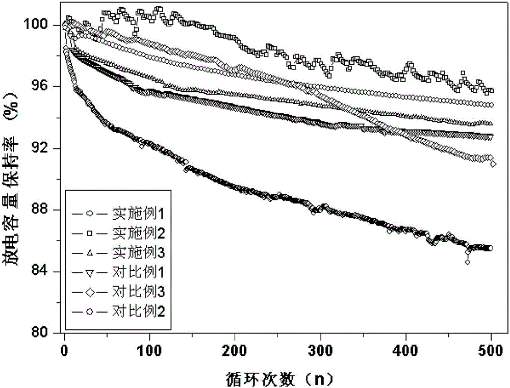

Embodiment 1

[0029] 1) Mix 93g of artificial graphite, 3g of conductive agent SP, 4g of LA132 binder and 200g of double distilled water to obtain negative electrode slurry;

[0030] At the same time, 43g of lithium hexafluoroaluminate, 43g of aluminum oxide, 7g of carbon nanotubes, 7g of polyvinylidene fluoride and 200g of N-methylpyrrolidone solvent were mixed uniformly to obtain a conductive composite slurry;

[0031] By vapor deposition method, methane gas is deposited on part A (the side length of which is 2 mm) of the surface of current collector copper foil (roughness 0.4 μm) by plasma chemical vapor deposition to obtain current collector A1, and then SiB4 is deposited by vapor phase method The current collector B1 (with a side length of 2 mm) is deposited on the part B of the surface of A1, and its deposition thickness is 1.0 μm.

[0032] After drying, apply the negative electrode slurry on the surface of B1 through a coating machine (the coating thickness is 120 μm), and obtain the...

Embodiment 2

[0034] 1) Mix 93g of artificial graphite, 3g of conductive agent SP, 4g of LA132 binder and 200g of double distilled water to obtain negative electrode slurry;

[0035] At the same time, 40g of lithium hexafluoroaluminate, 40g of aluminum oxide, 10g of graphene, 10g of polyvinylidene fluoride and 200g of N-methylpyrrolidone solvent were mixed uniformly to obtain a conductive composite slurry;

[0036] By vapor deposition method, ethane gas is deposited on part A (side length 0.1 mm) of the current collector copper foil (roughness 0.5 μm) by plasma chemical vapor deposition to obtain current collector A1, and then the Mg2Si Part B (with a side length of 0.1 mm) deposited on the surface of A1 is deposited to obtain a current collector B1, and its deposition thickness is 0.5 μm.

[0037] After drying, apply the negative electrode slurry on the surface of B1 by a coating machine (the coating thickness is 80 μm), and obtain the pole roll C after drying, and then coat the conductive...

Embodiment 3

[0039] 1) Mix 93g of artificial graphite, 3g of conductive agent SP, 4g of LA132 binder and 200g of double distilled water to obtain negative electrode slurry;

[0040] At the same time, 45g of lithium hexafluoroaluminate, 45g of alumina, 5g of vapor-grown carbon fiber, 5g of polyvinylidene fluoride and 200g of N-methylpyrrolidone solvent were mixed uniformly to obtain a conductive composite slurry;

[0041] By vapor deposition method, natural gas is deposited on part A (side length 2 mm) of the surface of current collector copper foil (roughness 1.0 μm) by plasma chemical vapor deposition to obtain current collector A1, and then the particle size is obtained by gas phase method. 200nm of silicon powder is deposited on part B of the surface of A1 (with a side length of 2 mm) to obtain a current collector B1 with a deposition thickness of 2 μm.

[0042] After drying, apply the negative electrode slurry on the surface of B1 through a coating machine (the coating thickness is 200...


PUM

PropertyMeasurementUnit
surface roughnessaaaaaaaaaa
thicknessaaaaaaaaaa
thicknessaaaaaaaaaa

Abstract

The invention discloses a high-capacity lithium ion battery negative electrode plate and a preparation method thereof. The negative electrode plate comprises a negative electrode current collector, and a base coat, an active substance layer and a conductive composite layer which are coated on the surface of the negative electrode current collector. The negative electrode plate is characterized in that the base coat makes a silicon material and a carbon material deposit on the surface of the current collector to form unit cells in the staggered directions through a vapor deposition method, and the silicon material and the carbon material are arranged in the unit cells in a staggered mode. The silicon material and the carbon material deposit on the surface of the current collector through the vapor deposition method and are high in density and large in adhesive force with the current collector, and the process is controllable; meanwhile, the carbon material deposits on the periphery of the silicon material, the electric conductivity of the electrode plate is improved, the expansion rate of the electrode plate is decreased, and therefore the energy density and cycle performance of a lithium ion battery are improved.

Description

technical field [0001] The invention relates to a lithium-ion battery, in particular to a high-capacity lithium-ion battery negative pole piece and a preparation method thereof, belonging to the technical field of lithium-ion batteries. Background technique [0002] With the rapid development of electric vehicles and their digital electronic products, lithium-ion batteries are required to have higher energy density. The negative electrode material is an important part of the lithium-ion battery. The negative electrode of the current commercial lithium-ion battery mainly uses carbonaceous materials such as natural graphite and artificial graphite. However, the theoretical capacity of these graphitized carbonaceous carbon materials is only 372mAh / g, which greatly limits the further improvement of the overall capacity of the battery. Although alloy anode materials such as silicon base have high theoretical capacity (4200mAh / g), they have become a research hotspot in recent yea...

Claims


Application Information

Patent Timeline
Patent Type & Authority Applications(China)
IPC IPC(8): H01M4/04H01M4/134H01M4/1395H01M4/36H01M4/38H01M4/62H01M10/0525
CPCH01M4/0404H01M4/0428H01M4/134H01M4/1395H01M4/366H01M4/386H01M4/624H01M4/625H01M10/0525Y02E60/10
Inventor 袁万颂
Owner XIAMEN RIZHEN POWER TECH CO LTD
Learn More