Laser heating friction welding method

A laser heating and friction welding technology, which is applied in laser welding equipment, welding equipment, metal processing equipment, etc., can solve the problems that the heating area is not easy to control, the workpiece is not suitable for friction welding, and the heat-affected zone softens, etc., to achieve green production efficiency Effects of environmental protection, rich content and variety, expansion of content and variety

Active Publication Date: 2019-10-18
BEIJING UNIV OF TECH
View PDF9 Cites 0 Cited by
  • Summary
  • Abstract
  • Description
  • Claims
  • Application Information

AI Technical Summary

Problems solved by technology

As we all know, friction welding uses the frictional heat generated by the friction between the workpieces to achieve welding. In order to generate enough frictional heat, the welding process will exert a lot of pressure between the workpieces and generate a large frictional torque, so the welding equipment is complex and Bulky, with high strength and stiffness requirements for weldments
For workpieces with small cross-sectional areas such as thin-walled tubes, discs, and flakes, the workpiece will be flattened and unstable due to the clamping force and friction pressure of the fixture. At the same time, the cross-sectional area is too small to prevent Generates enough frictional heat to make such workpieces less suitable for friction welding
[0003] Limited by the power of the main motor of the friction welding machine, it is difficult to greatly increase the size of the joint surface of the friction welding workpiece. To solve this problem, there are friction welding with auxiliary heat sources such as induction heating friction welding, conductive heating friction welding, and flame heating friction welding. Although the auxiliary heating method increases the heat of the joint to a certain extent, the disadvantages are also obvious: the heating area is large, the heating area is not easy to control, the heat-affected zone softens severely, and the operation is inconvenient. Flame heating may also cause a large amount of carburization of the weld
[0004] Although friction welding has unique advantages in the field of joining dissimilar materials, its inherent characteristics determine that it still has great difficulties in welding the following materials: materials with high high-temperature strength, low plasticity, and good thermal conductivity; materials with large differences in physical properties Materials, such as stainless steel-copper, hard alloy-steel, etc., active metals (such as titanium, zirconium)-steel, etc.; there are oxide films or coatings, infiltration layers, etc. on the surface; the friction coefficient is too small (such as cast iron, brass, etc.) s material
[0005] Usually friction welding cannot add welding materials, which is a shortcoming for improving the quality of dissimilar joints, because many dissimilar metals need to rely on intermediate additive materials to buffer the difference in structure and performance
[0006] In summary, although friction welding can obtain good joint quality and high welding efficiency, due to its selectivity to welding materials and welding structures, the application range of traditional friction welding is limited to some specific industries and products, and the application area is seriously affected. limit

Method used


Image

  • Laser heating friction welding method
  • Laser heating friction welding method
  • Laser heating friction welding method

Examples


specific Embodiment approach 1

[0030] Specific embodiment one: present embodiment is carried out as follows:

[0031] 1. The end face of the pipe fittings to be welded is deoxidized and dirt-treated until the surface of the workpiece reveals the true color of the metal.

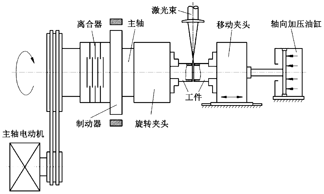
[0032] 2. If figure 1 , firmly install the workpiece to be welded on the chuck, reserve a gap of 1mm between the end faces of workpiece 1 and workpiece 2 to be welded, turn on the power to rotate workpiece 1 at a rotation speed of 500r / min, and check the concentricity and roundness of the workpiece .

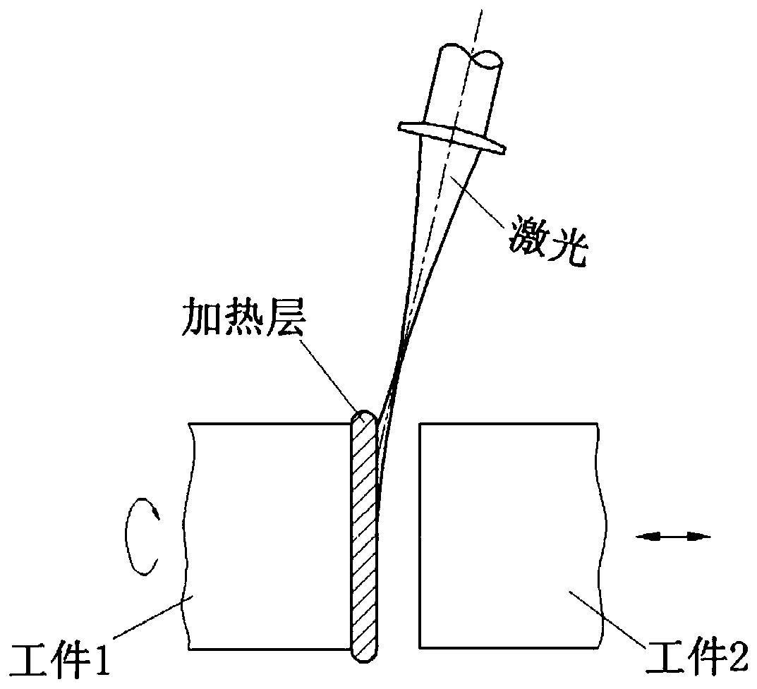
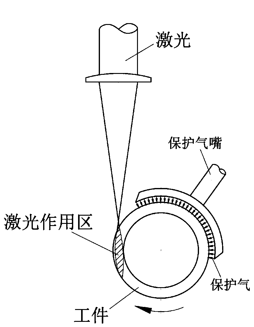
[0033] 3. If figure 2 , the beam deflection angle (the angle between the laser beam and the workpiece end face) is set to 20°, and the spot size is 0.5mm 2 ~40mm 2 Between, the laser power is 1000W. like image 3 , adjust the laser action position near the tangent line of the ring, set up argon gas protection in the welding area, the gas flow rate is 30L / min, and the gas protection range is 150° in the angular direction.

[0034] 4...

specific Embodiment approach 2

[0036] Specific embodiment 2: The difference between this embodiment and specific embodiment 1 is that the laser spot shape can be multi-spot, rectangular spot, arc-shaped spot, etc. in addition to circular, such as Figure 4 , other steps and parameters are the same as those in Embodiment 1.

specific Embodiment approach 3

[0037] Embodiment 3: The difference between this embodiment and Embodiment 1 is that a beam of laser heats two workpieces 1 and 2 with opposite rotation directions at the same time, such as Figure 5 , other steps and parameters are the same as those in Embodiment 1.


PUM


Abstract

The invention relates to the field offriction welding, and provides a friction welding heating method by using laser. Particularly, before welding, end faces of work piecesare radiated by the laser, so as to make the surface layer in ahigh temperature or micro melting state, then friction and upsetting process are conducted swiftly, so as to extrude liquid metals and parts of thermoplastic metals, finally the connection is formed through diffusion and recrystallization. According to the method, the unique advantages of highdensity of laser energy, precise and controllable airspace and time domain, and the characteristics of good quality of friction welding joint and high production efficiency and the like are synthetically utilized. The method has the advantages that external input energy is used as a main energy source; the required pressure and torque of friction welding are greatly decreased; the requirementfora welding equipment is reduced; processing ranges of traditional friction welding are expanded: the heterogenetic materials with big difference in physical and chemical characteristics, workpieces with small stiffness, thin walls and minor diameters, and workpieces with low friction coefficient, with-surface layer, high temperature and strength are welded.

Description

technical field [0001] The invention relates to the field of friction welding and provides a novel compound friction welding method using laser external energy as the main heat source. Background technique [0002] Friction welding has unique advantages such as good joint quality, high welding dimensional accuracy, green and high efficiency, and is suitable for welding dissimilar materials. It has been widely used in aerospace, petrochemical, power electronics, automotive industries and other industries. As we all know, friction welding uses the frictional heat generated by the friction between the workpieces to achieve welding. In order to generate enough frictional heat, the welding process will exert a lot of pressure between the workpieces and generate a large friction torque, so the welding equipment is complicated and Bulky, while there are high strength and rigidity requirements for weldments. For workpieces with small cross-sectional areas such as thin-walled tubes,...

Claims


Application Information

Patent Timeline
Patent Type & Authority Patents(China)
IPC IPC(8): B23K26/346
Inventor 杨武雄吕俊霞邹江林徐洁洁
Owner BEIJING UNIV OF TECH
Why Eureka
Try Eureka