Zirconium cladding surface resistant to high temperature and oxidation ZrCrFe/AlCrFeTiZr composite gradient coating preparing technology

A technology of high temperature oxidation resistance and preparation technology, which is applied in the direction of metal material coating technology, coating, ion implantation plating, etc., can solve problems such as explosion and inability to ensure structural integrity, achieve high strength and hardness, and improve high temperature resistance Oxidation performance, effect of releasing internal stress

Active Publication Date: 2017-12-26
田雨
View PDF6 Cites 23 Cited by
  • Summary
  • Abstract
  • Description
  • Claims
  • Application Information

AI Technical Summary

Problems solved by technology

Zirconium alloy reacts with high-temperature steam, so that zirconium alloy can no longer guarantee its structural integrity under uncontrollable conditions, and in serious accidents (such as loss of coolant accident (LOCA)), a large amount of hydrogen is released, which is easy to cause explosion, etc. nuclear accident
It shows that the existing fuel cladding can no longer meet the requirements of accident safety, so it is urgent to develop a new type of anti-high temperature oxidation nuclear fuel cladding material or develop the surface modification technology of zirconium alloy cladding material

Method used


Image

  • Zirconium cladding surface resistant to high temperature and oxidation ZrCrFe/AlCrFeTiZr composite gradient coating preparing technology
  • Zirconium cladding surface resistant to high temperature and oxidation ZrCrFe/AlCrFeTiZr composite gradient coating preparing technology

Examples


Embodiment 1

[0023] a. Clean the substrate material: Use water sandpaper with different roughness to zirconium alloy (Zr 4 alloy) substrate for grinding and polishing; then use acetone and ethanol as solvents to degrease and degrease and clean in an ultrasonic instrument; then clean with deionized water, dry and put into a vacuum chamber, the vacuum degree is -4 Pa;

[0024] b. Treatment of the substrate before deposition: keep the vacuum chamber vacuum -4 Under the condition of Pa, the reverse sputtering was used for 10 minutes to clean the zirconium alloy substrate; the reverse sputtering bias voltage was -500 V; the reverse sputtering gas was Ar; the reverse sputtering pressure in the vacuum chamber was 3.0 Pa;

[0025] c. Pre-sputtering: Keep the vacuum chamber vacuum -4 Under the condition of Pa, pre-sputtering was used to clean each target for 15 minutes to remove impurities on the target surface; the pre-sputtering power was 110 W; the pre-sputtering bias was -110 V; the pre-sput...

Embodiment 2

[0029] a. Clean the substrate material: Use water sandpaper with different roughness to zirconium alloy (Zr 4 alloy) substrate for grinding and polishing; then use acetone and ethanol as solvents to degrease and degrease and clean in an ultrasonic instrument; then clean with deionized water, dry and put into a vacuum chamber, the vacuum degree is -4 Pa;

[0030] b. Treatment of the substrate before deposition: keep the vacuum chamber vacuum -4 Under the condition of Pa, the reverse sputtering was used for 10 minutes to clean the zirconium alloy substrate; the reverse sputtering bias voltage was -500 V; the reverse sputtering gas was Ar; the reverse sputtering pressure in the vacuum chamber was 3.0 Pa;

[0031] c. Pre-sputtering: Keep the vacuum chamber vacuum -4 Under the condition of Pa, pre-sputtering was used to clean each target for 15 minutes to remove impurities on the target surface; the pre-sputtering power was 110 W; the pre-sputtering bias was -110 V; the pre-sput...

Embodiment 3

[0034] a. Clean the substrate material: Use water sandpaper with different roughness to zirconium alloy (Zr 4 alloy) substrate for grinding and polishing; then use acetone and ethanol as solvents to degrease and degrease and clean in an ultrasonic instrument; then clean with deionized water, dry and put into a vacuum chamber, the vacuum degree is -4 Pa;

[0035] b. Treatment of the substrate before deposition: keep the vacuum chamber vacuum -4 Under the condition of Pa, the reverse sputtering was used for 10 minutes to clean the zirconium alloy substrate; the reverse sputtering bias voltage was -500 V; the reverse sputtering gas was Ar; the reverse sputtering pressure in the vacuum chamber was 3.0 Pa;

[0036] c. Pre-sputtering: Keep the vacuum chamber vacuum -4 Under the condition of Pa, pre-sputtering was used to clean each target for 15 minutes to remove impurities on the target surface; the pre-sputtering power was 110 W; the pre-sputtering bias was -110 V; the pre-sput...


PUM


Abstract

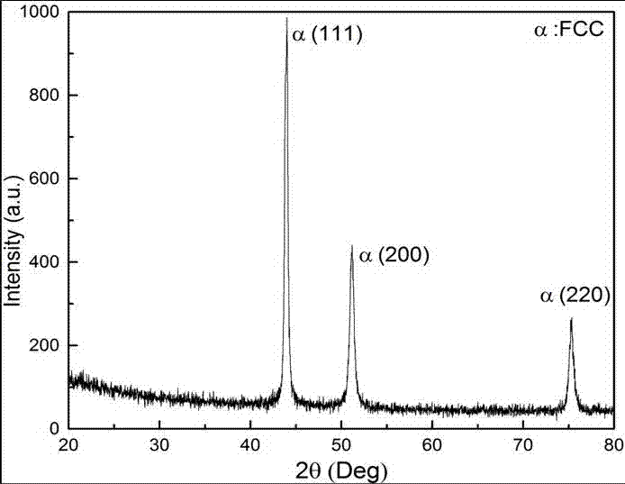
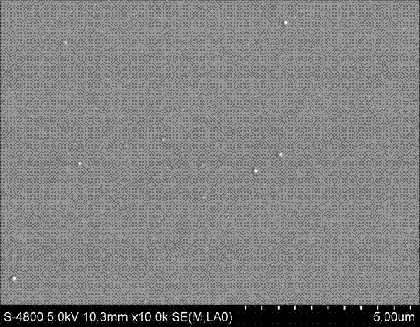
The invention discloses a zirconium cladding surface resistant to high temperature and oxidation ZrCrFe/AlCrFeTiZr composite gradient coating preparing technology. Ultrahigh vacuum multitarget co-sputtering technique is adopted, a ZrCrFe/AlCrFeTiZr composite gradient alloy resistant to high temperature and oxidation protecting coating is prepared on the surface of a zirconium alloy base body, and the zirconium cladding surface resistant to high temperature and oxidation ZrCrFe/AlCrFeTiZr composite gradient coating preparing technology comprises the steps of predepositional treatment, bias voltage anti-splash washing and ZrCrFe/AlCrFeTiZr composite gradient alloy coating deposition. The preparing process of the composite coating is divided into two steps, the first step is to prepare ZrCrFe gradient transition layer coating, in a deposited ZrCrFe transition layer, the atomic percentage content of Zr element is changed from the gradient of 100 at%-35 at% in the thickness direction, the atomic percentage content of Cr element is changed from the gradient of 0 at%-33 at% in the thickness direction, and the atomic percentage content of Fe element is changed from the gradient of 0 at%-33 at% in the thickness direction; the second step is to prepare a AlCrFeTiZr high-entropy alloy coating, in a deposited AlCrFeTiZr high-entropy alloy coating, the atomic percentage content of Al element is controlled in 0.5 at%-1.0at %, and the atomic percentage of other elements is between 10 at%-35 at%. Bonding force of the coating prepared by the technology is excellent, the surface is dense and uniform, and the coating has excellent performance such as high strength, resistance to high temperature and oxidation and irradiation resistance.

Description

technical field [0001] The invention belongs to the technical field of surface modification of zirconium alloy cladding of reactor nuclear fuel, and in particular relates to a ZrCrFe / AlCrFeTiZr composite gradient alloy prepared on the surface of zirconium alloy by adopting multi-target co-sputtering technology with dense and uniform surface structure, high-temperature oxidation resistance and excellent mechanical properties Coating preparation method. Background technique [0002] As an efficient, economical and durable energy source, nuclear energy has significant advantages in solving energy crisis and solving environmental problems. At present, zirconium alloys are widely used in reactor nuclear fuel cladding tubes and structural materials due to their small neutron absorption cross section, good corrosion resistance and mechanical properties, and good compatibility with uranium fuel. Zirconium alloy reacts with high-temperature steam, so that the zirconium alloy can no ...

Claims


Application Information

Patent Timeline
Patent Type & Authority Applications(China)
IPC IPC(8): C23C14/35C23C14/16C23C14/02
CPCC23C14/022C23C14/165C23C14/352
Inventor 刘波蒲国林黎蔚
Owner 田雨
Why Eureka
Try Eureka