A kind of ceramic membrane coating method

A ceramic membrane and ceramic technology, which is applied in the field of ceramic membrane separation, can solve the problems of uneven coating of transition layer and filter layer, high equipment requirements, and low paint utilization rate, so as to reduce artificial individual differences, simple coating device, The effect of short coating time

Active Publication Date: 2020-11-13
ZHEJIANG SCI-TECH UNIV
View PDF7 Cites 0 Cited by
  • Summary
  • Abstract
  • Description
  • Claims
  • Application Information

AI Technical Summary

Problems solved by technology

[0004] However, due to the uneven coating of the transition layer and the filter layer and the uneven thickness of the film layer during the production process of the ceramic membrane, there are many defects in the practical application of the ceramic membrane: film layer cracking, film layer shedding, poor membrane filtration accuracy, Wide pore size distribution, low permeate flux, fast flux decay, serious membrane fouling and low separation efficiency
However, the paint utilization rate of air spraying is low, the spray dispersion is large, and the equipment requirements are high

Method used


Image

  • A kind of ceramic membrane coating method

Examples


Embodiment 1

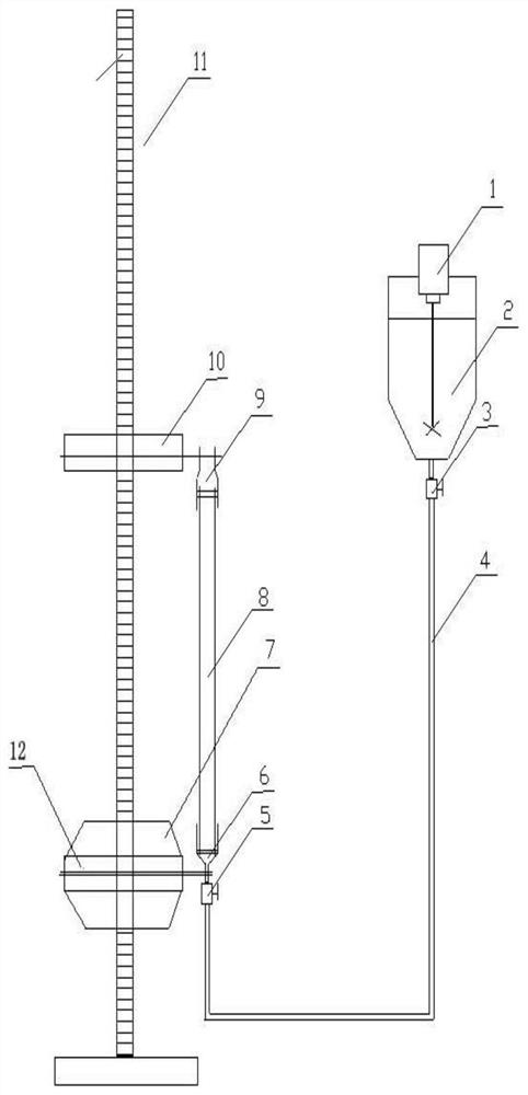
[0025] First prepare a special device for installing the ceramic support body, as attached figure 1 As shown, the special device includes a slurry tank 2, a valve, and a sealing joint, wherein the slurry tank 2 is connected to the lower sealing joint 6 through a hose 4; corresponding to the lower sealing joint 6, there is another one corresponding to the upper sealing joint in the vertical direction. The sealing joint 9; the lower sealing joint 6 and the upper sealing joint 9 are installed on the lifting and fixing column 11, and the upper sealing joint 9 is connected to the lifting and fixing column 11 through the upper sealing joint fixing rod 10; the lower sealing joint 6 is connected to the lifting and fixing column 11 through the lower sealing joint fixing rod 12 is connected to the lifting and fixing column 11; there is a lifting motor 7 on the lifting and fixing column 11, and is located below the upper sealing joint fixing rod 10; the electric agitator 1 is arranged in ...

Embodiment 2

[0028]Mix 10-100 μm silicon carbide with sintering aids, binders and solvents according to the mass percentage of 15wt%: 4.5wt%: 0.5wt%: 80wt%, the sum of the mass percentages of each component is 100%; sintering aids, particles The diameter ranges from 10 to 100 μm; the binder is composed of one or more of polyvinyl alcohol, methyl cellulose, carboxymethyl cellulose, hydroxypropyl methyl cellulose, and hydroxyethyl cellulose; the solvent water A mixture formed with ethanol; mechanically stirred and mixed evenly and ball milled for 3-6 hours to obtain a slurry with good castability; install the two ends of the first ceramic support on the lower sealing joint 6 and the upper sealing joint 9 respectively; the prepared A good coating solution is added to the slurry tank 2. Under the action of the electric agitator 1, the slurry is mixed more evenly. Open the A valve, let the slurry flow to the B valve 5 through the hose 4, and ensure that the B valve 5 Higher than the liquid leve...

Embodiment 3

[0030] Mix 0.02-10 μm silicon carbide with sintering aids, binders, dispersants and solvents according to the mass percentage of 25wt%: 6wt%: 3wt%: 3wt%: 63wt%; the particle size range of sintering aids is 0.02-10 μm; The binder is the same as the solvent in Example 1; the dispersant is composed of one or more of sodium hexametaphosphate, sodium citrate, polyacrylic acid, triethanolamine, and polymethacrylic acid amine; mechanically agitate and mix uniformly and ball mill for 6- 12h, obtain the slurry with good castability;

[0031] Install the two ends of the first ceramic support on the lower sealing joint 6 and the upper sealing joint 9 respectively, and then add the prepared slurry into the slurry tank 2. Under the action of the electric stirrer 1, the slurry mixing is more efficient. Evenly, open A valve 3, let the slurry flow to B valve 5 through the hose 4, and ensure that B valve 5 is higher than the slurry liquid level in the slurry tank 2, then open B valve 5, and th...


PUM

PropertyMeasurementUnit
particle diameteraaaaaaaaaa

Abstract

The invention relates to the technical field of ceramic membrane production, particularly to a ceramic membrane coating method, which comprises: installing a ceramic supporting body, preparing a slurry, and coating the ceramic supporting body, wherein the slurry is formed by mixing silicon carbide, a sintering aid, a binder and a solvent, and the method is mainly characterized in that the surfaceof the inner channel of the ceramic membrane is uniformly coated with the membrane coating liquid through the gravity action, the adhesion of the membrane coating liquid and the capillarity action onthe surface of the ceramic supporting body. According to the present invention, with the method, the plastic film purchasing cost can be eliminated, the manpower for the wrapping with the plastic filmand the peeling of the plastic film can be eliminated, the pollution of the difficultly-degraded plastic film on the environment can be reduced, the coating process is simple, the coating time is short (the one ceramic supporting body coating time only needs 1 min), the non-uniform membrane layer caused by the individual difference in workers can be reduced, and the incomplete coating phenomenoncannot be generated.

Description

technical field [0001] The invention relates to the technical field of ceramic membrane separation, in particular to a ceramic membrane coating method. [0002] technical background [0003] Ceramic membranes are widely used in special applications due to their advantages such as high mechanical strength, acid and alkali resistance, high temperature resistance, good chemical stability, resistance to organic solvents, good regeneration performance, simple separation process, low energy consumption, easy operation and maintenance, and long service life. Separation, chemical production and wastewater treatment, especially in the treatment of oily wastewater, the concentration of biological fermentation liquid, the removal of impurities in sugar industry, the deep purification of refined brine in chlor-alkali industry and tobacco extract. [0004] However, due to the uneven coating of the transition layer and the filter layer and the uneven thickness of the film layer during the ...

Claims


Application Information

Patent Timeline
Patent Type & Authority Patents(China)
IPC IPC(8): C04B35/565C04B35/622C04B35/64
CPCC04B35/565C04B35/62218C04B35/64
Inventor 陈锋涛俞三传
Owner ZHEJIANG SCI-TECH UNIV
Why Eureka
Try Eureka