Method for regenerating fluorination catalyst

A technology of fluorination catalyst and hydrogen fluoride, which is applied in the direction of catalyst regeneration/reactivation, physical/chemical process catalysts, chemical instruments and methods, etc. It can solve the problems of rapid decline in activity of fluorination catalysts, reduced activity, and easy loss of active metal chromium, etc. question

Active Publication Date: 2018-04-13
RUYUAN DONGYANG LIGHT FLUORIDE CO LTD
View PDF3 Cites 2 Cited by
  • Summary
  • Abstract
  • Description
  • Claims
  • Application Information

AI Technical Summary

Problems solved by technology

[0005] For the current fluorination catalysts during the operation of industrial devices, the surface of the fluorination catalysts is prone to carbon deposition, causing some of the pores on the surface to be blocked and the active sites to be covered, thereby greatly reducing its catalytic activity; at the same time, the surface of the fluorination catalysts is Contaminated harmful impurities also reduce its activity and significantly increase by-products; and the traditional regeneration method is not enough to regenerate the fluorination catalyst during the regeneration process, the active metal chromium is easily lost during the regeneration process, and the activity of the regenerated fluorination catalyst decreases The technical problems such as faster, the present invention provides a kind of regeneration method of new fluorination catalyst, described regeneration method first removes the harmful impurity (metal oxide such as potassium oxide, sodium oxide) accumulated on the surface of fluorination catalyst by pickling, then Calcined in an oxidizing gas to remove carbon deposits, then soaked in the active replenishing liquid to reload the fluorinated catalyst with active substances, and finally activated

Method used


Image

  • Method for regenerating fluorination catalyst
  • Method for regenerating fluorination catalyst

Examples


preparation example Construction

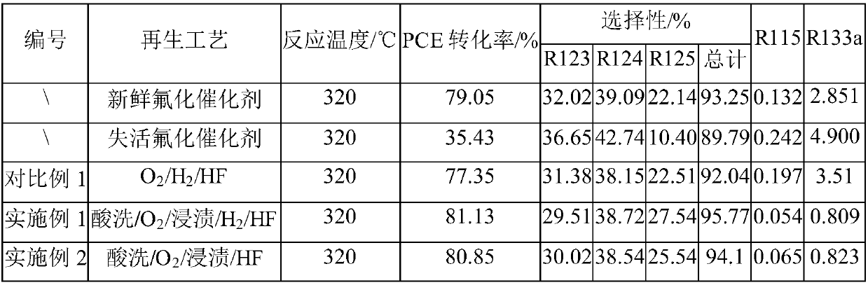
[0073] Preparation of fresh fluorination catalyst

[0074] Weigh 500g CrCl 3 ·6H 2 O, 4.56g MgCl 2 , 4.42g InCl 3 , 10.13g CoCl 2 Dissolve in 11.45L deionized water, mix the mixed salt solution and ammonia water until the pH of the solution is 9, filter and wash, put the sample into an oven and dry it at 110°C for 6 hours, then transfer it to a roasting furnace, in N 2 Calcined at 350°C for 4 hours in the atmosphere, crushed and sieved the calcined sample, added 2% graphite (mass fraction) additive to mix evenly, and pressed into tablets to obtain a catalytic precursor.

[0075] Then, the above-mentioned catalyst precursor was loaded into a reactor, and a mixed gas of nitrogen and HF was introduced to fluorinate at 350° C. to prepare a fresh fluorination catalyst.

[0076] Preparation of deactivated fluorination catalyst

[0077] After the fresh fluorination catalyst was reacted for 1600 hours, the catalyst was heated to 300° C., and nitrogen gas at a temperature of 300°...
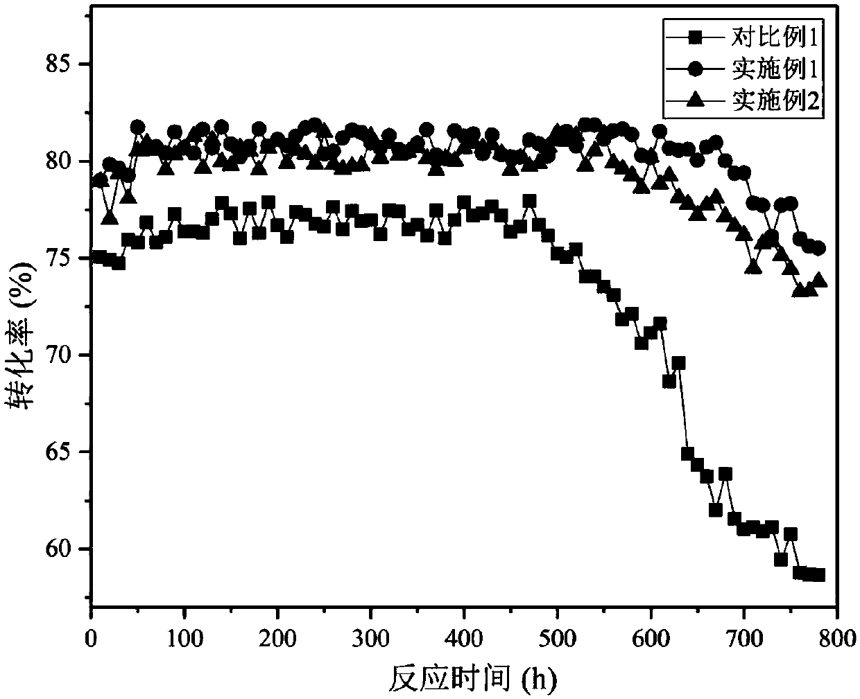
Embodiment 1

[0083] Soak the deactivated fluorination catalyst in a mixed solution of 10% hydrofluoric acid and 10% nitric acid for 2 hours, take it out, and dry it in an oven at 120°C for 10 hours;

[0084] The above-mentioned acid-washed fluorination catalyst was packed into a self-made fixed bed, and nitrogen gas with a temperature of 300° C. was introduced to purge the fluorination catalyst for 25 hours; nitrogen and oxygen (mass ratio 15° C. : 1) the mixed gas is calcined, the aeration time is 20h, thereafter the oxygen ratio is gradually increased until it is pure oxygen, and the temperature fluctuation of the fluorination catalyst is controlled to be less than 10°C, and the pure oxygen aeration time is 20h;

[0085] The above-mentioned calcined fluorination catalyst was placed in MgCl 2 and CrCl 3 The mixed solution (among them, MgCl 2 The mass percentage is 10%, CrCl 3 The mass percentage is 60%), soaked in 4h, take out, put in oven and dry at 120 ℃ for 10h;

[0086]Put the abo...

Embodiment 2

[0089] Soak the deactivated fluorination catalyst in a mixed solution of 10% hydrofluoric acid and 10% nitric acid for 2 hours, take it out, and dry it in an oven at 120°C for 10 hours;

[0090] The above-mentioned acid-washed fluorination catalyst was packed into a self-made fixed bed, and nitrogen gas with a temperature of 300° C. was introduced to purify the fluorination catalyst for 30 h; under normal pressure, the temperature was 300° C. nitrogen and oxygen (mass ratio 15: 1) The mixed gas is calcined, the aeration time is 20h, and then the proportion of oxygen is gradually increased until it is pure oxygen, and the temperature fluctuation of the fluorination catalyst is controlled to be less than 10°C, and the pure oxygen aeration time is 20h;

[0091] The above-mentioned calcined fluorination catalyst was placed in MgCl 2 and CrCl 3 The mixed solution (among them, MgCl 2 The mass percentage is 10%, CrCl 3 The mass percentage is 60%), soaked in 4h, take out, put in ov...


PUM


Abstract

The invention relates to a method for regenerating a fluorination catalyst. The method comprises the following steps: pickling an inactivated fluorination catalyst in an acid solution; calcining the pickled inactivated fluorination catalyst in an oxidizing gas; impregnating the calcined inactivated fluorination catalyst in an active supplementing solution; and regenerating the impregnated fluorination catalyst in a hydrogen fluoride-containing atmosphere, or regenerating the impregnated fluorination catalyst in a hydrogen-containing atmosphere and regenerating the impregnated fluorination catalyst in the hydrogen fluoride-containing atmosphere. The regeneration method has the following advantages: pickling can effectively remove metal impurities on the surface of the fluorination catalystand easily removes carbon deposited on the surface of the fluorination catalyst, so the fluorination catalyst is fully activated; and the calcined fluorination catalyst is impregnated in the active supplementing solution to make the fluorination catalyst fully obtain full new active sites in the regeneration process, so the catalytic activity of the regenerated fluorination catalyst is greatly improved. The regenerated fluorination catalyst has a good control effect on a byproduct R115 when applied to catalytic preparation of R125.

Description

technical field [0001] The invention relates to a regeneration treatment method of a catalyst, in particular to a regeneration method of a fluorination catalyst used in the gas-phase fluorination reaction of halogenated hydrocarbons and hydrogen fluoride. Background technique [0002] Hydrofluorocarbons are considered to be the best compounds to replace chlorofluorocarbons (freons). The main method of synthesizing fluorocarbons is gas-phase fluorination reaction. The key technology of this reaction is the development of solid catalysts. Catalysts are the core of this fluorocarbon production process. Due to the high reaction temperature in the production process, the reaction raw materials and products are easily Dehydrohalogenation occurs to produce olefin by-products, which causes carbon on the surface of the catalyst and accelerates the coking and deactivation of the catalyst. The carbon-containing residues or organic pollutants formed by the cracking or oligomerization o...

Claims


Application Information

Patent Timeline
Patent Type & Authority Applications(China)
IPC IPC(8): B01J23/86B01J23/94B01J38/60B01J38/12B01J38/64B01J38/10C07C17/20C07C19/08
Inventor 李义涛唐火强张宏清余航马鹏程
Owner RUYUAN DONGYANG LIGHT FLUORIDE CO LTD
Why Eureka
Try Eureka