Power plant flue gas steam latent heat and water recovery system, and recovery method and control method thereof

A water recovery and flue gas technology, applied in combustion methods, steam generation, separation methods, etc., can solve the problems of low recovery rate of water resources, complicated membrane material selection, unstable operation, etc., and achieve low cost and small heat transfer area , Improve the effect of water recovery rate

Inactive Publication Date: 2018-05-29
NORTH CHINA ELECTRIC POWER UNIV (BAODING)
View PDF6 Cites 8 Cited by
  • Summary
  • Abstract
  • Description
  • Claims
  • Application Information

AI Technical Summary

Problems solved by technology

Low-temperature condensation has the advantages of more technical experience, fast condensation speed, low material consumption, and simple manufacture. However, metal material heat exchangers are mostly used in the low-temperature condensation process, which will cause acid corrosion in the flue, and a single arrangement of heat exchangers cannot simultaneously Recover the latent heat and sensible heat of vaporization of water vapor in flue gas, and the recovery rate of water resources is low; membrane separation technology can recover both latent heat and sensible heat of vaporization of water vapor in flue gas to a certain extent, but there are complex screening of membrane materials and gypsum fouling Blocking problem, unstable operation, and high investment cost

Method used


Image

  • Power plant flue gas steam latent heat and water recovery system, and recovery method and control method thereof
  • Power plant flue gas steam latent heat and water recovery system, and recovery method and control method thereof

Examples


Embodiment Construction

[0029] The present invention will be further described below in conjunction with the accompanying drawings and specific embodiments. It should be emphasized that the following description is only exemplary and not intended to limit the scope of the invention and its application.

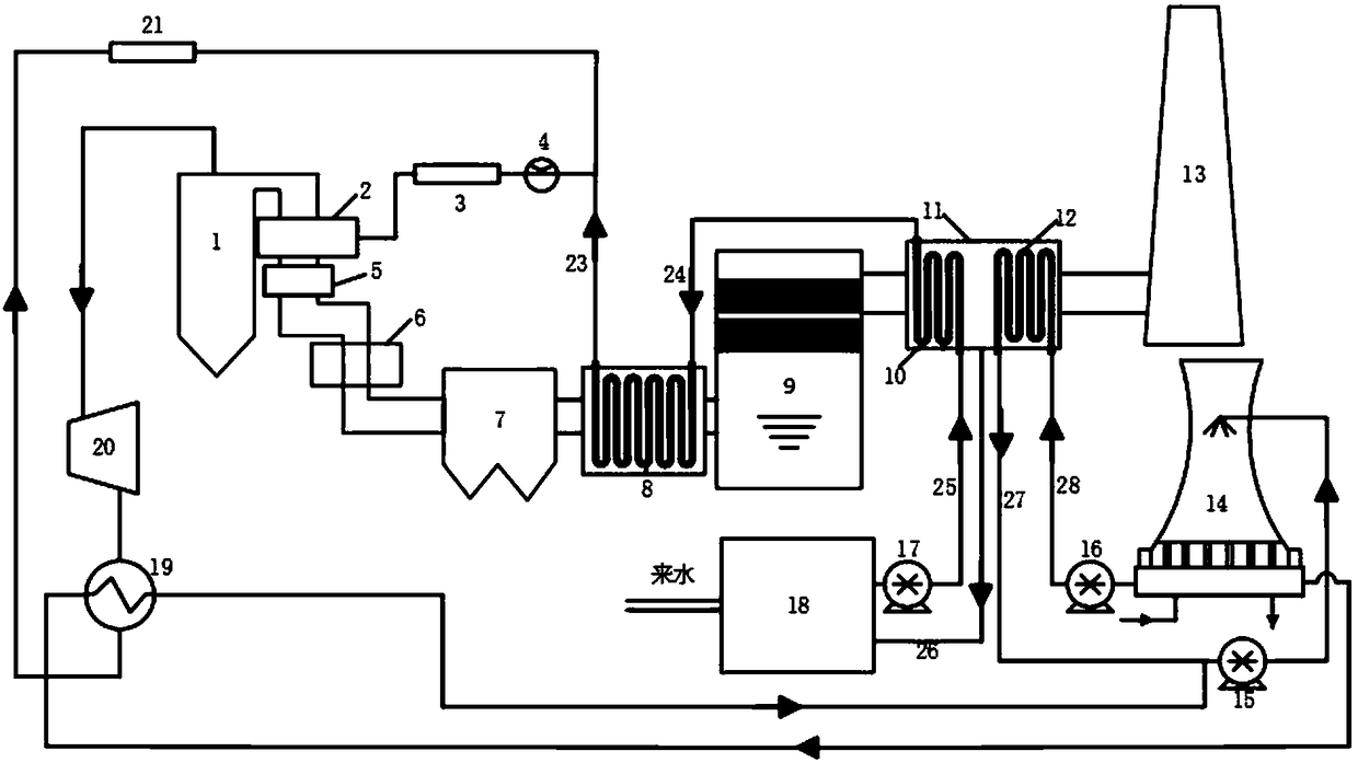
[0030] Such as figure 1 As shown, the water vaporization latent heat and water recovery system in the flue gas of the power plant includes an annular low-finned tube heat exchanger 8 and a heat exchange box 11;

[0031] The back end of economizer 2 of boiler 1 is connected to SCR denitrification system 5, air preheater 6, electrostatic precipitator 7, and desulfurization tower 9 in sequence; steam from boiler 1 enters steam turbine 20, condenser 19, and condenser 19 and The low-pressure heater 21 is connected, and the condenser 19 is also connected to the sump at the bottom of the circulating water cooling tower 14 through pipelines;

[0032] The flue gas inlet and outlet of the annular low-finned ...


PUM


Abstract

The invention belongs to the field of waste heat resource recovery and particularly relates to a power plant flue gas steam latent heat and water recovery system, and a recovery method and control method thereof. Boiler feedwater passes shell-tube heat exchangers and an annular low finned tube heat exchanger in sequence to be preheated and conducts heat exchange with flue gas in front of a desulfurizing tower. The inlet flue-gas temperature of the desulfurizing tower can be effectively reduced. The desulfurization efficiency can be improved. The preheated boiler feedwater is directly deliveredto a deaerator. Heating energy consumption of the deaerator on the boiler feedwater can be reduced. Flue gas behind the desulfurizing tower makes contact with a cooling medium in the continuous two-stage heat exchangers and can recover vaporization latent heat and sensible heat of water vapor in saturated flue gas simultaneously. When the flue gas temperature is lowered to below the dew point ofwater vapor, the concentration of hazardous substances such as SO2 and NOX in discharged smoke can be effectively reduced, and condensate water can also be used as a water resource to be recovered. The power plant flue gas steam latent heat and water recovery system is simple in structure, low in investment and operating cost and capable of bringing remarkable economic benefits for an enterprise and has good environmental and social benefits.

Description

technical field [0001] The invention belongs to the field of recovery of waste heat resources, in particular to a system for recovering steam latent heat and water in flue gas of a power plant, a recovery method and a control method, and is mainly applicable to power plants adopting wet desulfurization. Background technique [0002] Electric power enterprises are an important part and pillar industry of my country's national economy, and the pattern of coal-based power will exist for a long time, but most of the regions rich in coal resources in my country lack water. develop. [0003] The limestone-gypsum wet flue gas desulfurization process is considered as the preferred configuration for flue gas desulfurization of coal-fired power units due to its ultra-high desulfurization efficiency, mature technology, good quality desulfurized gypsum as a by-product, stable operation and convenient maintenance. However, after desulfurization, the humidity of the flue gas is relatively...

Claims


Application Information

Patent Timeline
Patent Type & Authority Applications(China)
IPC IPC(8): F23J15/00F23J15/02F23J15/06F22D1/50F01K11/02
CPCF01K11/02F22D1/50F23J15/006F23J15/022F23J15/025F23J15/06F23J2215/20F23J2217/102Y02E20/30Y02P80/15
Inventor 马双忱向亚军陈嘉宁武凯
Owner NORTH CHINA ELECTRIC POWER UNIV (BAODING)
Why Eureka
Try Eureka