In-situ growth and doping modification method for metal oxide nanometer catalyst

A nano-catalyst, in-situ growth technology, applied in metal/metal oxide/metal hydroxide catalysts, physical/chemical process catalysts, chemical instruments and methods, etc. problems such as force difference, to achieve the effect of controllable size and morphology, smooth and uniform surface, and strong bonding force of film base

Inactive Publication Date: 2018-06-05
INST OF METAL RESEARCH - CHINESE ACAD OF SCI
View PDF5 Cites 6 Cited by
  • Summary
  • Abstract
  • Description
  • Claims
  • Application Information

AI Technical Summary

Problems solved by technology

The metal catalyst coated on the surface of the honeycomb ceramic substrate has poor bonding force with the substrate, and it is easy to fall off from the surface of the honeycomb substrate under heat, humidity, vibration and corrosive environments, resulting in a decrease in catalyst performance and service life. Secondary repair or replacement of the honeycomb matrix increases the cost of use
Although the metal catalyst integrated with the ceramic substrate is not easy to fall off, the active crystal surface area exposed to the environment is significantly reduced, which directly affects its catalytic conversion efficiency. This requires the development of a metal catalyst that does not affect its catalytic performance. effective method
[0004] At present, the reports on metal oxide nanocatalyst materials mainly include hydrothermal method, microwave method, mechanical synthesis method, electrochemical synthesis method, sputtering method, co-precipitation method, etc., but the above methods have high cost and complicated process to varying degrees. , Not easy for industrial application, poor crystallinity, easy to agglomerate, easy to fall off, easy to produce toxic gas, difficult to control the product shape, etc., can not meet the needs of the application
Although the preparation of metal oxides by micro-arc oxidation has been reported (Jiang et al, "Highly Efficient Nanoarchitectured Ni 5 TiO 7 Catalyst for Biomass Gasification"ACSAppl.Mater.Interfaces 2012,4,4062-4066), but it only reported the growth of Ni-Ti-O on the surface of rod-shaped metal substrates, for the doping modification and Metal substrates of different shapes and specifications have not been studied, and these aspects are crucial for the practical application of metal oxide nanocatalyst materials

Method used


Image

  • In-situ growth and doping modification method for metal oxide nanometer catalyst
  • In-situ growth and doping modification method for metal oxide nanometer catalyst
  • In-situ growth and doping modification method for metal oxide nanometer catalyst

Examples


Embodiment 1

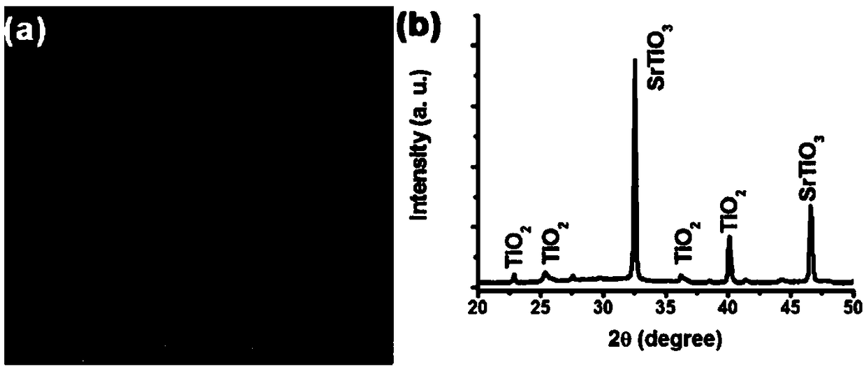
[0048] This example is SrTiO 3 The in-situ growth of nanoparticles on the surface of the Ti sheet metal substrate is as follows:

[0049] 1. Add 1L of deionized water to the beaker, and add 15.26g of Na 2 B 4 o 7 10H 2 O and 10.74g Sr(CH 3 COO) 2 1 / 2H 2 O, after mixing evenly, add 3.00g EDTA-2Na and 3.00g NaOH, and continue stirring for 1h to obtain the electrolyte solution for micro-arc oxidation.

[0050] 2. Using industrial pure titanium (Gr1) as the substrate, first cut the titanium sheet into a suitable size, and then pretreat it. Put the Ti sheet in acetone for 15 minutes to sonicate, remove the oil on the surface, then rinse the residual acetone with deionized water, and then put the Ti sheet in H at room temperature. 2 O:HNO 3: HF=5:4:1 (volume ratio) for 60s to remove the oxide layer on the surface, and finally wash it with deionized water and absolute ethanol.

[0051] 3. Put the electrolyte obtained in step 1 into a stainless steel electrolytic cell, then ...

Embodiment 2

[0057] This example is CeO 2 The in-situ growth of nanoparticles on the surface of Ti sheet and Ti mesh metal substrate is as follows:

[0058] 1. Add 1L deionized water to the beaker, and add 25.09g Na 3 PO 4 12H 2 O and 12.97 g Na 2 B 4 o 7 10H 2 O, add 15.86g Ce(CH 3 COO) 3 , continue stirring for 1h.

[0059] 2. Use industrial pure titanium as the substrate to pretreat it. place the base in H 2 O:HNO 3 :HF=5:4:1 (volume ratio) for 60s, then washed with deionized water and absolute ethanol.

[0060] 3. Put the electrolyte obtained in step 1 into an electrolytic cell, and use the pretreated industrially pure titanium as an anode electrode for micro-arc oxidation to perform micro-arc oxidation. Its current density is 10A / dm 2 , the time of micro-arc oxidation is 15min.

[0061] 4. Heat the sample obtained in step 3 at 950°C for 30 minutes, then air cool to room temperature to obtain CeO 2 nanoparticles.

[0062] CeO grown by the above method 2 The phase comp...

Embodiment 3

[0065] This embodiment is (Ni 1-x co x ) 5 TiO 7 The in-situ growth of nanowires on the surface of the Ti sheet metal substrate is as follows:

[0066] 1. Add 1L deionized water to the beaker, and add 38.14g Na 3 PO 4 12H 2 O and 12.97 g Na 2 B 4 o 7 10H 2 O, after mixing evenly, add 14~20g Ni(CH 3 COO) 2 2H 2 O and 1~10gCo(CH 3 COO) 2 2H 2 O, continue to stir for 30min.

[0067] 2. Use industrial pure titanium as the substrate to pretreat it. place the base in H 2 O:HNO 3 : HF=5:4:1 (volume ratio) for 60s, then washed 4 times with deionized water and 2 times with absolute ethanol.

[0068] 3. Put the electrolyte obtained in step 1 into an electrolytic cell, and use the pretreated industrially pure titanium as an anode electrode for micro-arc oxidation to perform micro-arc oxidation. Its current density is 10A / dm 2 , the time of micro-arc oxidation is 10min.

[0069] 4. Put the sample obtained in step 3 in a tube furnace and anneal at 850°C for 30 minutes...


PUM

PropertyMeasurementUnit
diameteraaaaaaaaaa
lengthaaaaaaaaaa
particle diameteraaaaaaaaaa

Abstract

The invention relates to the technical fields of nucleation of a metal oxide nanometer catalyst, growth control, doping modification, environmental catalytic purification, micro-arc oxidization, nanometer materials and nano-technologies, in particular to an in-situ growth and doping modification method for the metal oxide nanometer catalyst. According to the in-situ growth and doping modificationtechnology for the metal oxide nanometer catalyst, a micro-arc oxidization method is mainly utilized for directly growing a metal oxide nanometer catalyst material on the surface of a metal substrate,and the metal oxide nanometer catalyst material is subjected to doping modification. The prepared metal oxide nanometer catalyst is good in crystallinity, large in active area, relative uniform in size, uniform in growth and distribution, and applicable to the fields of automobile tail gas treatment, denitration and desulfurization treatment, industrial waste gas treatment, CO catalytic oxidization and relevant environmental catalytic purification.

Description

technical field [0001] The invention relates to the fields of metal oxide catalyst nucleation and growth control, doping modification, environmental catalytic purification, micro-arc oxidation, nanomaterials and nanotechnology, and in particular relates to in-situ growth and doping modification of a metal oxide nanocatalyst method. Background technique [0002] At present, with the continuous development of the economy, a series of environmental pollution problems caused by it are becoming more and more serious, especially the abnormal climate and smog that have occurred continuously in recent years. These environmental pollutions mainly come from the emission of harmful substances in automobile exhaust, incompletely combusted CO in industrial waste gas, various incompletely combusted hydrocarbons, nitrogen oxides, sulfur oxides, etc. The removal of these harmful substances currently mainly relies on noble metal catalysts (such as: Pt, Pd, etc.) with good catalytic performa...

Claims


Application Information

Patent Timeline
Patent Type & Authority Applications(China)
IPC IPC(8): C25D11/26C25D11/34B01J23/04B01J23/10B01J23/75
CPCB01J23/002B01J23/04B01J23/10B01J23/75B01J2523/00C25D11/026C25D11/26C25D11/34B01J2523/47B01J2523/845B01J2523/847
Inventor 刘宝丹姜亚南刘小元王柯张兴来刘鲁生姜辛
Owner INST OF METAL RESEARCH - CHINESE ACAD OF SCI
Why Eureka
Try Eureka