Solar cell module and manufacturing method thereof

A technology of solar cells and modules, applied in the field of solar cells, which can solve the problems of extremely high requirements for instruments and equipment, reduction of the effective active area of ​​photoelectric generation, and occupied effective area, so as to reduce the ineffective area, high space utilization rate, and save space Effect

Active Publication Date: 2018-09-18
HUAZHONG UNIV OF SCI & TECH +1
View PDF4 Cites 6 Cited by
  • Summary
  • Abstract
  • Description
  • Claims
  • Application Information

AI Technical Summary

Problems solved by technology

However, in the traditional solar cell module, the connection between the two sub-cells needs to occupy an effective area, resulting in a reduction in the effective

Method used


Image

  • Solar cell module and manufacturing method thereof
  • Solar cell module and manufacturing method thereof
  • Solar cell module and manufacturing method thereof

Examples


preparation example Construction

[0039] The invention provides a method for preparing a solar cell module, comprising the following steps:

[0040] (1) Prepare a patterned bottom electrode on the substrate; the patterned bottom electrode includes several closely spaced bottom electrode units, and the bottom electrode unit includes two bottom electrode blocks, and the two bottom electrode blocks pass through the first A connection block is connected to form the first Z-shaped bottom electrode unit, and several first Z-shaped bottom electrode units arranged at equal intervals are the patterned bottom electrodes. The material selected for the first connection block and the bottom electrode The selected materials are the same; the distance between the bottom electrode units is preferably not more than 1 mm; the substrate of the bottom electrode can be glass, polyethersulfone resin (PES), polyethylene terephthalate (PET) or polyethylene For ethylene naphthalate (PEN), the bottom electrode can be conductive glass (...

Embodiment 1

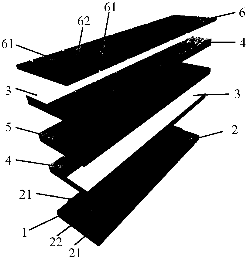
[0049] The solar cell module provided in this embodiment, the schematic diagram of its internal structure, such as figure 1 As shown, 1-substrate; 2-patterned bottom electrode; 21-bottom electrode block; 22-first connection block; 3-electron transport layer; 4-hole transport layer; 5-photoactive layer; 6- Patterned top electrode, 61-top electrode block; 62-second connection block; from bottom to top:

[0050] Patterned bottom electrode: the first Z-shaped bottom electrode unit arranged closely at equal intervals on the substrate, each bottom electrode unit consists of two bottom electrode blocks and a first connection block connecting the two electrode blocks Composition, the two bottom electrode blocks are connected and form the first zigzag;

[0051] The first interface layer: including a hole transport layer and an electron transport layer, the electron transport layer and the hole transport layer are in direct contact and respectively cover both sides of the first connect...

Embodiment 2

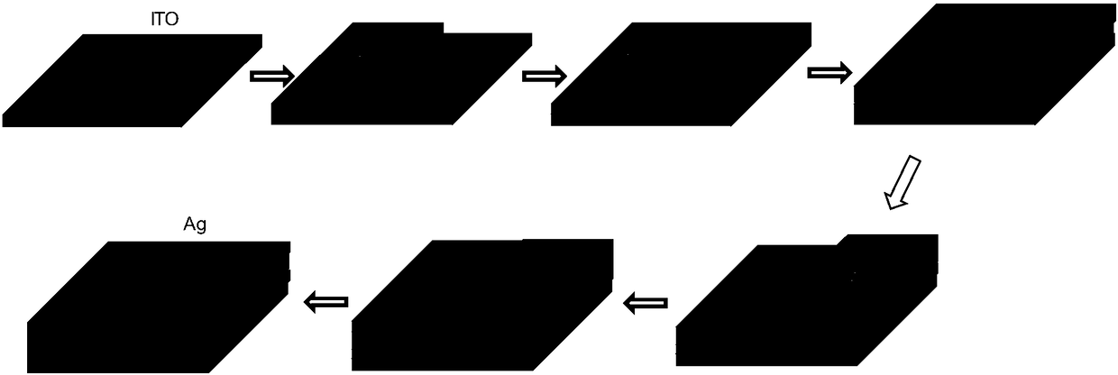
[0065] In this embodiment, the bottom electrodes are etched from ITO glass, and the patterns are arranged in a "Z" shape.

[0066] In the solar cell module, the hole transport layer below adopts a spin-coating process, and a strip of nickel oxide precursor solution is coated on the substrate, and then placed on a hot stage to sinter to form a dense nickel oxide film. This film is used to block electrons and collect holes.

[0067] In the solar cell module, the electron transport layer below adopts the spin-coating process. First, a layer of PEIE aqueous solution is spin-coated, and then a layer of CTAB:PCBM chloroform solution is spin-coated to form a two-layer film for collecting electrons and blocking holes.

[0068] In the solar cell module, the photoactive layer is spin-coated perovskite solution, and then sintered at 100°C to form a light-absorbing layer of about 200nm.

[0069] The upper hole transport layer and electron transport layer are also spin-coated, and Spiro a...


PUM


Abstract

The invention belongs to the field of solar cells, and particularly relates to a solar cell module and a manufacturing method thereof. The solar cell module comprises multiple serially connected sub-cells. Each sub-cell comprises a base electrode, an electronic transmission layer, an optical active layer, a hole transmission layer and a top electrode successively from the bottom to the top. The polarities of any two adjacent sub-cells are opposite to each other on the serial connection circuit of the solar cell module. The base electrodes of any two adjacent sub-cells on the serial connectioncircuit are directly connected with each other or directly connected with the top electrodes. According to the invention, middle ineffective area used for connecting the sub-cells can be effectively reduced; space filling factors of the module are improved; meanwhile, contact resistance of upper and lower electrodes is eliminated; and performance of the cell is further improved. According to the invention, it is potentially possible to achieve highly-efficient large-area solar cells.

Description

technical field [0001] The invention belongs to the field of solar cells, and more specifically relates to a solar cell module and a manufacturing method thereof. Background technique [0002] The gradual depletion and burning of traditional energy sources such as coal, oil, and natural gas have caused great pollution to the environment, breaking the ecological balance of the earth, resulting in abnormal climate and frequent occurrence of major natural disasters in recent years. Therefore, this forces people to search for clean and renewable energy sources. Among them, solar energy is a representative of green energy because of its clean, inexhaustible, and inexhaustible characteristics, and has attracted widespread attention. [0003] At present, the highest efficiency of inorganic silicon-based solar cells reaches 24%, gradually approaching the theoretical upper limit of 30%. But in terms of marketization, the total output of inorganic solar cells is less than 0.1% of th...

Claims


Application Information

Patent Timeline
IPC IPC(8): H01L31/05H01L31/048H01L31/18
CPCH01L31/048H01L31/05H01L31/18Y02E10/50Y02P70/50
Inventor 周印华孟伟覃飞王文蒋友宇
Owner HUAZHONG UNIV OF SCI & TECH
Why Eureka
Try Eureka