
Dielectric material continuous microwave sintering or melting forming method and equipment

A technology of microwave sintering and molding method, applied in microwave heating, lighting and heating equipment, electrical components and other directions, can solve the problems of difficult operation and maintenance, high equipment investment and production cost, greenhouse gas emission environment, etc., to reduce production investment and The effect of production operation cost, improving production efficiency and product quality, reducing emissions and environmental pollution

Inactive Publication Date: 2019-10-25
徐林波
View PDF0 Cites 1 Cited by
  • Summary
  • Abstract
  • Description
  • Claims
  • Application Information

AI Technical Summary

Problems solved by technology

Its disadvantages are: 1. The length is limited, which affects the output and quality of its products; 2. The thermal insulation performance is poor, and the energy loss is large; 3. The sintering temperature is low, and it cannot be used for material melting; 4. The service life is short, and operation and maintenance more difficult
In addition, there is another kind of annular rotary hearth furnace, because its bottom is an annular flat plate, so it can only be used for sintering of certain materials but not for its melting, and the structure of this annular rotary hearth furnace is extremely complicated and easy to deform , difficult to maintain and extremely expensive
[0005] In addition, the current large-scale melting of glass is carried out by putting loose glass batch materials with poor thermal conductivity on the surface of the molten glass, and using surface flame heating in the glass melting pool.
Its main disadvantages are: 1. The thermal efficiency is extremely low, the highest is only about 30%; 2. Greenhouse gas emissions and pollution are serious; 3. The investment is large and the production environment is harsh; 4. The melting rate is very low and the melting speed is slow
Its disadvantages are: 1. The drying, thermal decomposition and sintering process and production equipment are very complicated, with low thermal efficiency, high equipment investment and production costs; 2. The service life of equipment (especially rotary kiln sintering equipment) is short and difficult to operate and maintain ; 3. It will cause a large amount of greenhouse gas emissions and environmental pollution
The disadvantages are: 1. High sintering temperature and low thermal efficiency; 2. It is difficult to build a very long kiln, with large heat loss and poor production environment; 3. Using combustion heating will cause a large amount of greenhouse gas emissions and environmental pollution
However, it is not an optimized technical solution for ordinary soda-lime-silica glass and cement and ceramic materials containing a certain proportion of microwave absorbing components.

Method used


Image

  • Dielectric material continuous microwave sintering or melting forming method and equipment
  • Dielectric material continuous microwave sintering or melting forming method and equipment
  • Dielectric material continuous microwave sintering or melting forming method and equipment

Examples


Embodiment Construction

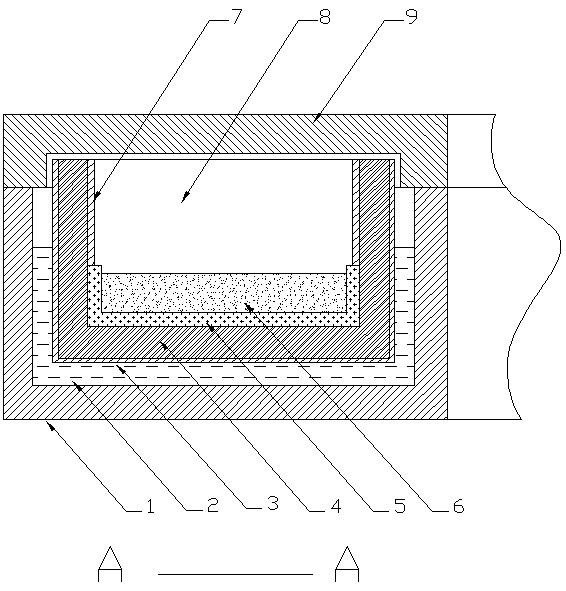
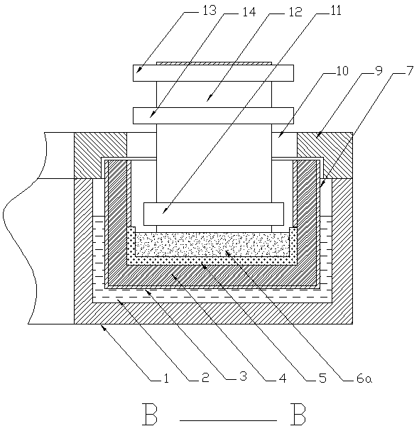
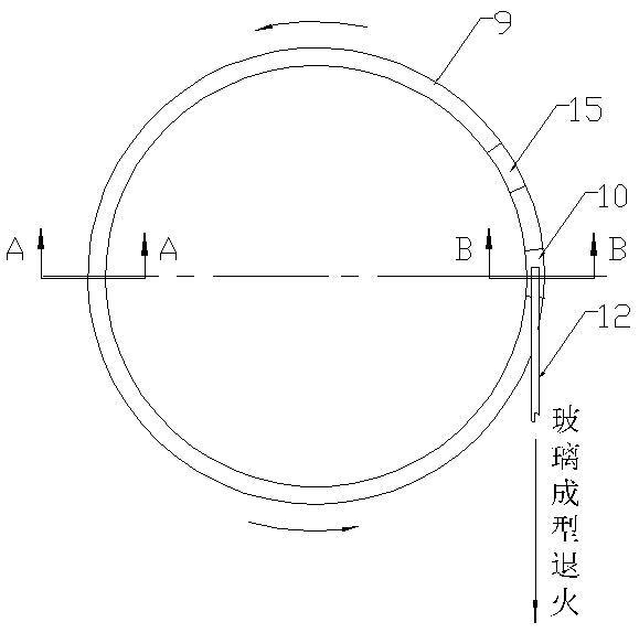
[0020] figure 1 , figure 2 , image 3 Among them, the microwave oven adopts a structure layer of metal shell microwave reflective material layer 3 / insulation material layer 4 / microwave transmission refractory material layer 5, which is combined to form the bottom structure of the microwave oven; The feed port 15 on the annular furnace roof 9 is continuously and uniformly laid and covered with microwave-absorbing dielectric raw materials 6 (such as ceramic raw materials, cement raw materials, glass batch materials, etc.) that need to be sintered or melted. On the refractory material layer 5; through the microwave source (not shown in the figure) arranged on the stationary and fixed annular furnace top 9 or the side of the furnace, the microwave is introduced into the microwave oven cavity 8, and the microwave is transmitted through direct radiation and reflection. Uniform radiation on the bottom of the furnace; the dielectric material on the uppermost layer of the furnace bo...


PUM


Abstract

The invention provides a dielectric material continuous microwave sintering or melting forming method and equipment. The dielectric material continuous microwave sintering or melting forming method ischaracterized in that structure layers which comprise a metal shell microwave reflection material layer / a heat preservation material layer / a microwave transmission refractory material layer are adopted to combine and form a furnace bottom structure of a microwave oven; the furnace bottom is enabled to continuously run, and through a feeding hole formed in the top of a static fixed furnace top, dielectric raw materials which are required to be sintered or fused, and can absorb microwaves are continuously and uniformly laid and covered on the microwave transmission refractory material layer; and through a microwave source arranged on the static and fixed furnace top or the furnace side, microwaves are guided into a furnace cavity of the microwave oven, and the microwaves are uniformly radiated on the furnace bottom through direct irradiation and reflection; and the dielectric raw materials at the uppermost layer at the bottom of the furnace are heated by first absorbing microwaves, andthe microwaves which are not completely absorbed are finally absorbed by the dielectric raw materials after being reflected in the metal shell in the oven cavity of the microwave oven, so that the purpose of sintering or melting the dielectric raw materials capable of absorbing the microwaves at normal temperature is achieved.

Description

technical field [0001] Microwave heating application technology and equipment. Background technique [0002] Microwave sintering and melting is a method of using the special wave band of microwave to couple with the basic fine structure of the material to generate heat. The dielectric loss of the material makes the material as a whole heated to the sintering temperature or melting temperature to densify the sintering or melting method. It has the characteristics of fast speed, high energy utilization rate, high heating efficiency, safety, sanitation and pollution-free, and can improve the uniformity and yield of products. Improving the microstructure and performance of sintered materials or melted materials has become a hot spot in the field of material sintering. new research hotspot. [0003] However, due to many dielectric materials, such as certain ceramic materials, cement raw materials, glass batch materials, etc., the change with temperature is very drastic. Their d...

Claims


Application Information

Patent Timeline
Patent Type & Authority Applications(China)
IPC IPC(8): F27B7/10F27B7/34F27B7/42H05B6/80H05K9/00
CPCF27B7/10F27B7/34F27B7/42H05B6/80H05K9/0001
Inventor 徐林波
Owner 徐林波
Learn More