NP0 type dielectric ceramic with high dielectric constant
A high dielectric constant, dielectric ceramic technology, applied in the direction of fixed capacitor dielectrics, circuits, capacitors, etc., can solve the problem of high sintering temperature, achieve the effect of low sintering temperature, stable temperature coefficient, and improved chemical stability
- Summary
- Abstract
- Description
- Claims
- Application Information
AI Technical Summary
Problems solved by technology
Method used
Image
Examples
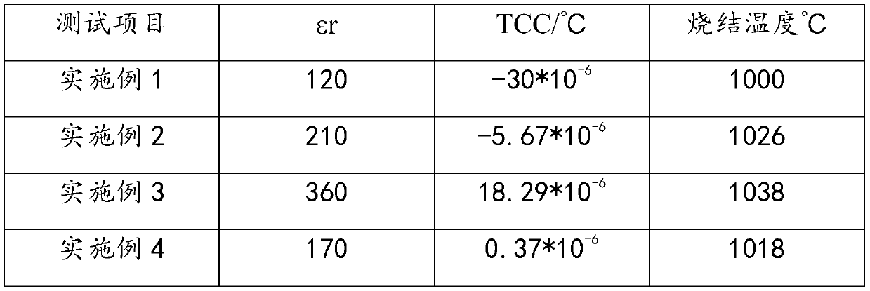
Embodiment 1
[0030] A kind of high dielectric constant NP0 type dielectric ceramics, comprising the following raw materials by weight: 5g of magnesium metatitanate (MgTiO 3 ), 5g of calcium titanate (CaTiO 3 ), 5g of titanium dioxide (TiO 2 ), 5g of neodymium trioxide (Nd 2 o 3 ), 50g of sintering aids and 5g of modified additives, the sintering aids are preferably boron oxide (B 2 o 3 ), the modification additive is preferably zirconium dioxide (ZrO 2 ).
[0031] Add grinding balls and ball milling media to the above mixed powder, wherein the mass ratio of the mixed powder, grinding balls and ball milling media is a ratio of 1:1:2, the grinding balls are zirconia ceramic balls, and the ball milling media is Deionized water: After the mixed powder, grinding balls and deionized water are ball milled and calcined, polyvinyl alcohol (PVA) with a mass percentage of 2% is added.
Embodiment 2
[0033] A kind of high dielectric constant NP0 type dielectric ceramics, comprising the following raw materials by weight: 100g of magnesium metatitanate (MgTiO 3 ), 60g of calcium titanate (CaTiO 3 ), 30g of titanium dioxide (TiO 2 ), 120g of neodymium trioxide (Nd 2 o 3 ), 60g of sintering aids and 60g of modified additives, the sintering aids are preferably bismuth oxide (Bi 2 o 3 ), the modification additive is preferably niobium pentoxide (Nb 2 o 5 ).
[0034] Add grinding balls and ball milling media to the above mixed powder, wherein the mass ratio of the mixed powder, grinding balls and ball milling media is a ratio of 1:1:2, the grinding balls are zirconia ceramic balls, and the ball milling media is Deionized water: After the mixed powder, grinding balls and deionized water are ball milled and calcined, polyvinyl alcohol (PVA) with a mass percentage of 2% is added.
Embodiment 3
[0036] A kind of high dielectric constant NP0 type dielectric ceramics, comprising the following raw materials by weight: 120g of magnesium metatitanate (MgTiO 3 ), 80g of calcium titanate (CaTiO 3 ), 50g of titanium dioxide (TiO 2 ), 180g of neodymium trioxide (Nd 2 o 3 ), 80g of sintering aids and 120g of modified additives, the sintering aids are preferably bismuth oxide (Bi 2 o 3 ), the modification additive is preferably niobium pentoxide (Nb 2 o 5 ).
[0037] Add grinding balls and ball milling media to the above mixed powder, wherein the mass ratio of the mixed powder, grinding balls and ball milling media is a ratio of 1:1:2, the grinding balls are zirconia ceramic balls, and the ball milling media is Deionized water: After the mixed powder, grinding balls and deionized water are ball milled and calcined, polyvinyl alcohol (PVA) with a mass percentage of 2% is added.
PUM
 Abstract
Description
Claims
Application Information
 - R&D
- Intellectual Property
- Life Sciences
- Materials
- Tech Scout
- Unparalleled Data Quality
- Higher Quality Content
- 60% Fewer Hallucinations
Browse by: Latest US Patents, China's latest patents, Technical Efficacy Thesaurus, Application Domain, Technology Topic, Popular Technical Reports.
© 2025 PatSnap. All rights reserved.Legal|Privacy policy|Modern Slavery Act Transparency Statement|Sitemap|About US| Contact US: help@patsnap.com


