Dilute nitric acid production process

A production process, dilute nitric acid technology, applied in the chemical industry, can solve problems such as easy to burn platinum mesh, difficult overall control, product acid concentration limit, etc.

Active Publication Date: 2019-12-10
SICHUAN GOLDEN ELEPHANT SINCERITY CHEM CO LTD
View PDF7 Cites 6 Cited by
  • Summary
  • Abstract
  • Description
  • Claims
  • Application Information

AI Technical Summary

Problems solved by technology

[0022] 1: The mixing of ammonia and air is not uniform, and the temperature difference of the oxidation furnace is large
Usually the main reason is that the ammonia-air mixer adopts simple straight pipe injection for mixing, and at the same time, the gas is fully distributed before entering the oxidation furnace, so the mixing of ammonia and air is not very uniform, and the temperature difference of the oxidation furnace is large (5-10 °C). The surface of the catalyst is a wavy hot spot
[0023] 2: Insufficient waste heat recovery, failure to fully recover ammonia oxidation waste heat and NO oxidation waste heat, the waste heat boiler only produces steam from the vertical waste boiler in the oxidation furnace, and the tail gas recovery energy is limited to the requirements of the expander and can only heat the tail gas To 380 ~ 400 ℃, so the recovered energy can only balance the compression power consumption of the four-in-one unit, and even a small amount of steam needs to be added from the outside to achieve steam balance
[0025] 1) The layout of the steam superheater and water evaporator is unreasonable, the absorption and utilization rate of the reaction heat is low, and the supply of superheated steam required by other units cannot be realized, and it is easy to burst due to overheating, which affects the production of the unit
[0026] 2) The nozzles on t...

Method used


Image

  • Dilute nitric acid production process
  • Dilute nitric acid production process
  • Dilute nitric acid production process

Examples


Embodiment 1

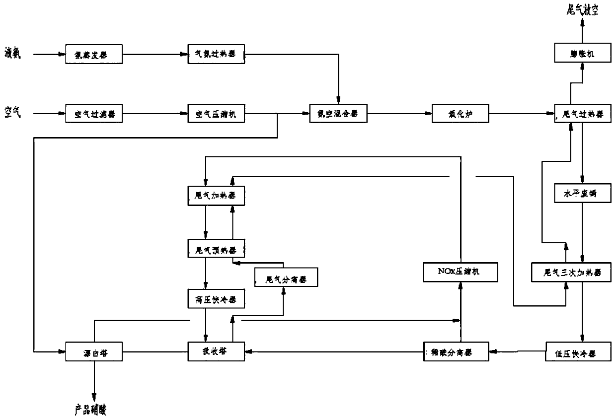
[0113] A set of 150,000 tons / year double pressurized dilute nitric acid production process:

[0114] 1: Process: The liquid ammonia from the boundary area enters the ammonia evaporator. There are two ammonia evaporators, namely ammonia evaporator A and ammonia evaporator B. Heat exchange steam, evaporated to 5.60bar abs gas ammonia. After the gas ammonia is separated from the entrained liquid droplets by the separator, it enters the gas ammonia superheater and is heated to 120°C with tail gas (steam is used when starting up). The superheated ammonia gas is sent through the ammonia filter and then sent to the ammonia-air mixer, where it is mixed with air in proportion to form an ammonia-air mixture.

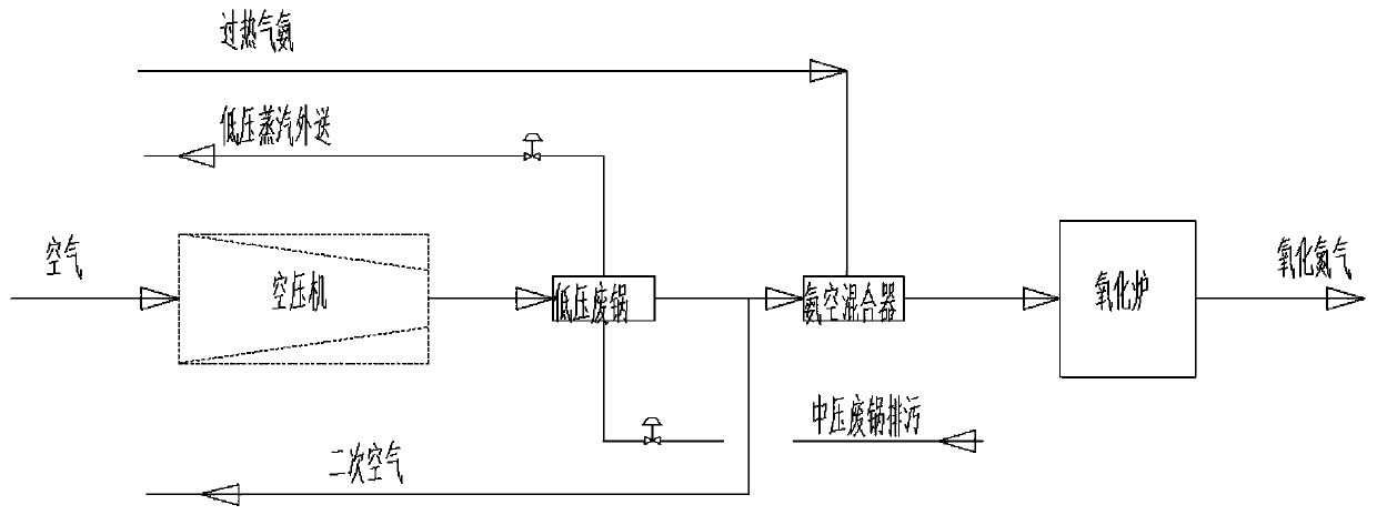
[0115] After the air passes through the filter, it enters the air compressor and is compressed to 4.2 bar abs by the air compressor. The compressed air passes through the low-pressure waste boiler, and the excess waste heat is used to generate low-pressure steam, while keeping th...


PUM


Abstract

The invention belongs to the field of chemical industry, and in particular, relates to a dilute nitric acid production process. The process includes the following steps: after ammonia evaporation andheating, adjusting the flow quantity, allowing gas ammonia to enter an ammonia-air mixer and uniformly mixing the gas ammonia with compressed air; allowing the ammonia-air mixture after mixing to enter an oxidation furnace, carrying out catalytic oxidation reaction on a platinum mesh surface, oxidizing ammonia into nitric oxide, recycling waste heat from process gas leaving the catalyst through awaste heat boiler and tail gas respectively, and then condensing by a low-pressure quick cooler, after separation of dilute acid, mixing the process gas with air from a bleaching tower, and then allowing the mixed gas to enter an oxidation nitrogen compressor; further increasing the temperature of gas through the compressed process gas; recycling waste heat of the compressed process gas, cooling,and then allowing the cooled process gas to enter an absorption tower; and carrying out a reaction of oxide of nitrogen in the absorption tower after absorption with water to generate nitric acid. Theprocess has the advantages of high nitrogen oxide absorption rate, low ammonia consumption, high acid concentration and low tail gas emission concentration, and can reach the standard without furthertreatment.

Description

technical field [0001] The invention belongs to the field of chemical industry, in particular to a dilute nitric acid production process. Background technique [0002] The production of dilute nitric acid is based on ammonia as a raw material. In the presence of a catalyst, ammonia and oxygen in the air undergo a directional catalytic reaction to generate nitric oxide (NO) and water. Nitric oxide is further oxidized to nitrogen dioxide (NO 2 ), nitrogen dioxide NO 2 Absorbed in water to generate nitric acid. Therefore, the industrial production of dilute nitric acid involves three main reaction processes, namely the oxidation of ammonia, the oxidation of nitrogen monoxide, and the absorption of nitrogen dioxide. The main reaction formula is as follows: [0003] 4NH 3 +5O 2 =4NO+6H 2 0+Q [0004] 2NO+O 2 =2NO 2 +Q [0005] 3NO 2 +H 2 O=2HNO 3 +NO+Q [0006] The NO generated by the absorption is then oxidized and then absorbed, and this cycle is carried out unti...

Claims


Application Information

Patent Timeline
IPC IPC(8): C01B21/40C01B21/26
CPCC01B21/26Y02P20/129
Inventor 李旭初王明权郭志刚刘朝慧雷林
Owner SICHUAN GOLDEN ELEPHANT SINCERITY CHEM CO LTD
Why Eureka
Try Eureka