Surface treatment method for power transmission shaft of speed reducer and coating

A technology of power transmission and surface treatment, which is applied in the direction of coating, metal material coating process, fusion spraying, etc., can solve the problems of reducing the bending fatigue life of parts, insufficient wear resistance of the shaft surface, and poor anti-corrosion effect, etc., to achieve The effect of ensuring uniformity

Inactive Publication Date: 2020-04-03
GUANGDONG INST OF NEW MATERIALS
View PDF6 Cites 5 Cited by
  • Summary
  • Abstract
  • Description
  • Claims
  • Application Information

AI Technical Summary

Problems solved by technology

However, electroplating hard chromium will reduce the bending fatigue life of the parts when they are subjected to large alternating loads, and its insufficient wear resistance will cause the shaft surface to be too smooth after long-term service to form a fluid lubricating film, thereby affecting the sealing performance of key components And service life, in addition, there are many microscopic cracks in hard chrome plating, and its anti-corrosion effect has been poor
The electroplating process also uses strong acid and harmful chemical materials in the process of treatment, which is harmful to the human body, and the waste discharge is very serious to the environment. It has been subject to more and more strict production control and production ban. The application of these processes is prohibited

Method used


Image

  • Surface treatment method for power transmission shaft of speed reducer and coating
  • Surface treatment method for power transmission shaft of speed reducer and coating
  • Surface treatment method for power transmission shaft of speed reducer and coating

Examples


Embodiment 1

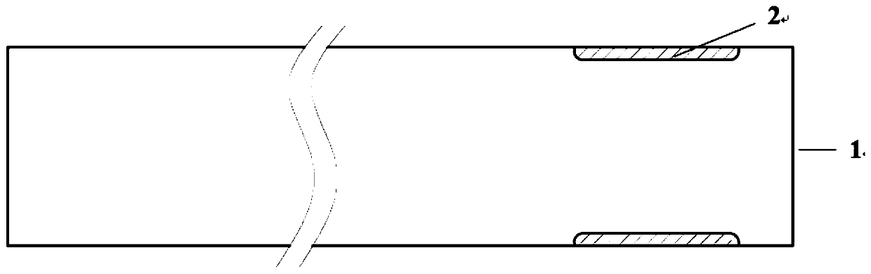
[0064] This embodiment provides a method for surface treatment of a power transmission shaft of a reducer, which includes the following steps:

[0065] (1) Degrease and degrease the 9310 steel workpiece processed with grooves with a depth of 0.15mm. The sprayed surface is roughened by sandblasting with zirconium corundum. The surface roughness in the groove was Ra=3.8 μm.

[0066] (2) Put the workpiece roughened by sandblasting in step (1) into the turntable and fix it. The non-spraying area is shielded and protected by high-temperature tape and fixtures, and the workpiece is preheated to 160°C with plasma flame flow under the condition of not feeding powder. ℃.

[0067] (3) Start the compressed air to cool the workpiece preheated in step (2), and at the same time open the auxiliary air flow device and the powder feeder, and start to move the spray gun for spraying after the powder feeding is stable. Cr with a particle size of 22-45 μm is used 2 o 3 Powder, plasma spray gu...

Embodiment 2

[0070] (1) Degrease and degrease the 15-5PH steel workpiece with a depth of 0.18mm. The sprayed surface is roughened by sandblasting with brown corundum. The sand grain size is 46#, the sandblasting pressure is 0.40MPa, and the sandblasting distance is 150mm , The inner surface roughness of the prefabricated groove is Ra=3.5μm.

[0071] (2) Put the workpiece roughened by sandblasting in step (1) into the turntable and fix it. Use high-temperature tape and fixtures for protection in the non-spraying area, and use the plasma flame to preheat the workpiece to 180°C under the condition of not feeding powder. .

[0072] (3) Start the compressed air to cool the workpiece preheated in step (2), and at the same time open the auxiliary air flow device and the powder feeder, and start to move the spray gun for spraying after the powder feeding is stable. Cr with a particle size of 10-30 μm is used 2 o 3 For powder, the current of the plasma spray gun is 630A, the argon gas is 45L / min...

Embodiment 3

[0075] (1) Degrease and degrease the 4340 steel workpiece with a groove depth of 0.20mm. The sprayed surface is roughened by sandblasting with white corundum. The inner surface roughness of the groove is Ra=3.9 μm.

[0076] (2) Put the workpiece roughened by sand blasting into the turntable and fix it. The non-spraying area is shielded and protected by high-temperature tape and fixtures. Under the condition of not feeding powder, the workpiece is preheated to 170°C by plasma flame flow.

[0077] (3) Start the compressed air to cool the workpiece, and at the same time turn on the auxiliary air flow device and the powder feeder, and start to move the spray gun for spraying after the powder feeding is stable. Cr with a particle size of 15-45 μm is used 2 o 3 For powder, the current of the plasma spray gun is 670A, the argon gas is 38L / min, the hydrogen gas is 12L / min, the powder feeding rate is 40g / min, the carrier gas is 4L / min, the workpiece speed is 450rpm, the spray distanc...


PUM

PropertyMeasurementUnit
depthaaaaaaaaaa
depthaaaaaaaaaa
surface roughnessaaaaaaaaaa

Abstract

The invention discloses a surface treatment method for a power transmission shaft of a speed reducer and a coating, and relates to the technical field of material surface treatment. The method comprises the steps: a to-be-sprayed area on the surface of the power transmission shaft of the speed reducer is machined to form a groove; then, the surface in the groove is activated and roughened througha sand blasting method; and then, a wear-resisting and friction-reducing coating is formed in the groove through direct spraying, wherein the speed reducer power transmission shaft is an input shaft or an output shaft. The groove is formed in the surface of the power transmission shaft of the speed reducer, the groove is used for restraining the coating deposited in the groove subsequently, and the groove structure can further prevent the coating from being extruded and damaged when the coating is subjected to grinding machining and oil seal sealing is installed in an interference mode in theaxial direction. According to the surface treatment method, the wear-resistant and friction-reducing coating can be formed through direct spraying in the groove and a bonding layer does not need to bearranged; an oxide skin of the surface to be sprayed is removed through surface sand blasting pretreatment so as to improve the surface activity and the surface roughness, and therefore, the bondingstrength between the coating and the groove is improved.

Description

technical field [0001] The invention relates to the technical field of material surface treatment, in particular to a surface treatment method and coating of a power transmission shaft of a reducer. Background technique [0002] The reducer is mainly used to reduce the speed and increase the torque of the electric motor, internal combustion engine or other high-speed running power through the intermeshing gear set or the use of worm and turbine transmission. It has been widely used in various fields of the national economy and defense industry, including aerospace, Metallurgy, nonferrous metals, coal, building materials, ships, water conservancy, electric power, construction machinery and petrochemical industries. For example, the reducer in the transmission system of a helicopter, its function is to reduce the high speed of the engine to the low speed of the rotor, and at the same time combine the power of one or more engines and transmit them to the main rotor, tail rotor ...

Claims


Application Information

Patent Timeline
Patent Type & Authority Applications(China)
IPC IPC(8): C23C4/134C23C4/02C23C4/11
CPCC23C4/02C23C4/11C23C4/134
Inventor 杨焜宋进兵曾威牛少鹏陈志坤邓春明邓畅光刘敏周克崧
Owner GUANGDONG INST OF NEW MATERIALS
Why Eureka
Try Eureka