Microstructure optical fiber capable of simultaneously transmitting optical information and optical energy

A technology of micro-structure optical fiber and optical information, which is applied in the field of laser energy transmission and optical fiber communication, and achieves the effects of low price, low mode dispersion and novel structure

Pending Publication Date: 2020-06-23
SOUTH CHINA NORMAL UNIVERSITY
View PDF5 Cites 2 Cited by
  • Summary
  • Abstract
  • Description
  • Claims
  • Application Information

AI Technical Summary

Problems solved by technology

At the same time, a large number of base stations are being deployed on a large scale, and the problem of power supply will become mor

Method used


Image

  • Microstructure optical fiber capable of simultaneously transmitting optical information and optical energy
  • Microstructure optical fiber capable of simultaneously transmitting optical information and optical energy
  • Microstructure optical fiber capable of simultaneously transmitting optical information and optical energy

Examples


Embodiment 1

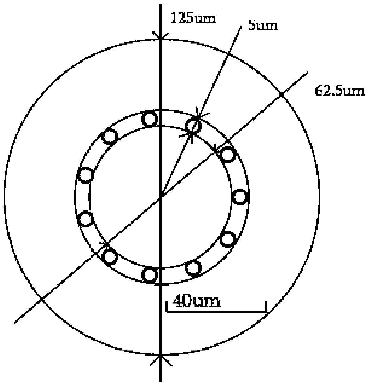
[0043] Such as figure 1 As shown, the present invention provides a microstructure optical fiber for the joint transmission of optical information and optical energy, and its structural design is completed by Comsol multi-physics simulation software. figure 1 The end view of the optical fiber is designed. The core of the optical fiber is a solid core, and the cladding is surrounded by periodically arranged air holes. The air holes are filled with air, which are air holes, and the air holes are embedded with the perfect matching layer. The core diameter is 62.5 μm, the cladding diameter is 125 μm, the cladding air hole diameter is 5 μm, the cladding air hole wall thickness is 0.5 μm, and the perfect matching layer size is 20 μm wide (not shown in the figure).

[0044] Specifically, the designed signal-energy co-transmission microstructure fiber is made of all-silicon material, and the core refractive index is shown in Table 1 below. The concept of signal-energy co-transmission s...

Embodiment 2

[0051] The invention provides a method for preparing a microstructured optical fiber that transmits optical information and optical energy together, comprising the following steps:

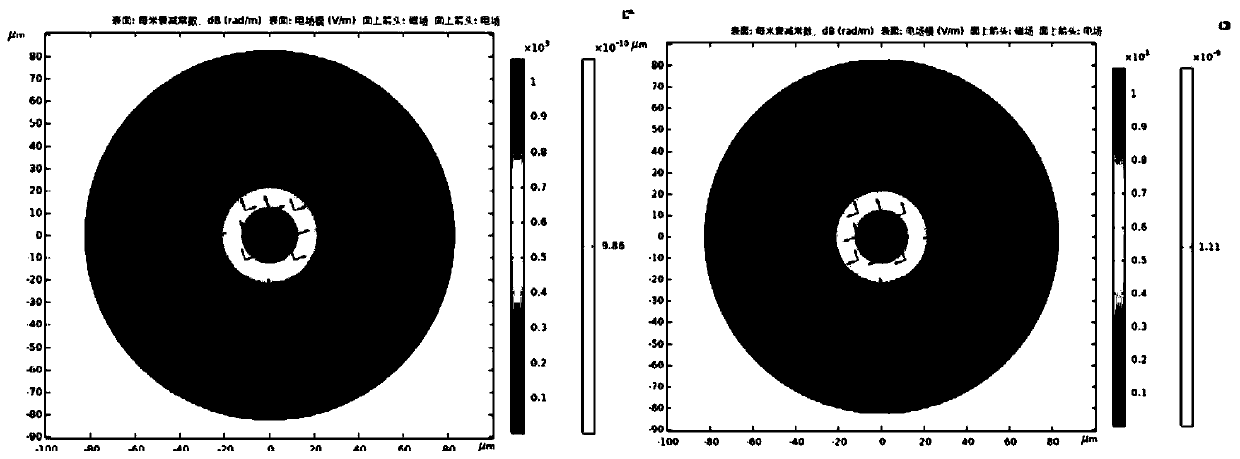
[0052] Step A: Import the designed signal-energy co-transmission microstructure fiber into Comsol software for physical field simulation analysis of its loss and mode field distribution;

[0053]Step B: Enlarge the optical fiber structure designed in step A according to the proportion of the cross-sectional view, select the appropriate sleeve and capillary, and arrange the optical fiber preform;

[0054] Step C: welding one end of the optical fiber preform obtained in step B to a sleeve with a slightly larger inner diameter and a similar outer diameter;

[0055] Step D: putting the optical fiber preform obtained in step C into a drawing tower as a whole for optical fiber drawing;

[0056] Step E: Leave the end of the drawn optical fiber long enough to wind the coil;

[0057] Specifically, in ste...

Embodiment 3

[0068] The present invention also provides a fusion splicing scheme for a large-core-diameter microstructure optical fiber that simultaneously transmits optical information and optical energy to be connected to an all-fiber signal energy co-transmission detection system, including the following steps:

[0069] Step A: Cut both ends of the signal-energy co-transmission microstructure fiber flat, use an optical fiber cutting machine, adjust appropriate cutting parameters, and control the number of cutting knives at 11-20;

[0070] Step B: splicing the two ends of the signal energy co-propagation microstructure fiber obtained in step A with the multimode pigtail matching the laser of the detection system used;

[0071] Step C: put the whole optical fiber obtained in step B into a loss measurement system to measure the splice loss.

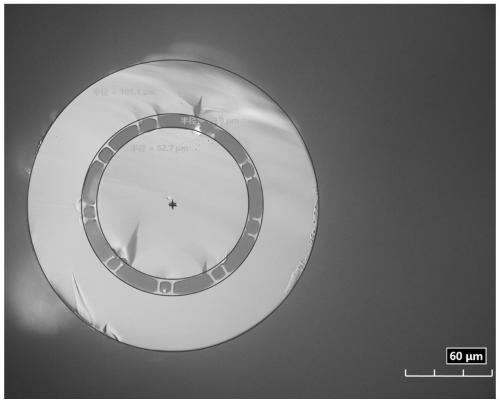
[0072] Such as Figure 4 As shown, specifically, the light cutting machine used in step A is a Fujikura CT105 fiber cutting machine, which is suitab...


PUM

PropertyMeasurementUnit
Core diameteraaaaaaaaaa
Cladding diameteraaaaaaaaaa
Diameteraaaaaaaaaa

Abstract

The invention discloses a microstructure optical fiber capable of simultaneously transmitting optical information and optical energy. A fiber core of the microstructure optical fiber is a solid core,a cladding is formed by surrounding periodically arranged air holes, and the air holes are embedded with a perfect matching layer. In order to prove the application prospect of the solid-core large-core-diameter microstructure optical fiber in the field of information and energy co-transmission, the microstructure optical fiber of which the length exceeds 1.37 km and the transmission loss is 2.26dB/km under the 976 nm waveband is actually drawn. In order to access an all-fiber information and energy co-transmission communication system, the problem of fusion welding is solved, the fusion welding loss is controlled to be 0.25-0.36 dB, and the problem of fusion welding point loss when the optical fiber is accessed to the all-fiber communication system is well solved. In conclusion, the invention aims to develop a long-distance photonic crystal fiber supporting energy-signal co-transmission and carry out communication system application verification.

Description

technical field [0001] The invention relates to the technical fields of laser energy transmission and optical fiber communication, in particular to a microstructured optical fiber for co-transmission of optical information and optical energy. Background technique [0002] As the two main driving forces for the development of mobile communications in the future, the mobile Internet and the Internet of Things provide broad application prospects for the fifth generation of mobile communications (5G). Faced with a thousand-fold increase in data traffic, hundreds of billions of device connections, and diverse business needs, 5G network construction faces many new challenges. In the 5G network, due to the high-frequency band and large-capacity characteristics of 5G, the coverage of base stations is greatly reduced, and the number of base stations that need to be deployed, especially indoor base stations, is greatly increased. Therefore, although the 5G network can provide up to 1...

Claims


Application Information

Patent Timeline
IPC IPC(8): G02B6/02G02B6/25G02B6/255C03B37/027
CPCG02B6/02295G02B6/02328G02B6/02395G02B6/255G02B6/25C03B37/027
Inventor 侯峙云李佳隆夏长明刘建涛周桂耀陈海娇张傲岩
Owner SOUTH CHINA NORMAL UNIVERSITY
Why Eureka
Try Eureka