
Multi-channel high-repetition-frequency large-dynamic-range distance and speed measurement laser radar method and device

A large dynamic range, lidar technology, used in measurement devices, radio wave measurement systems, instruments, etc., can solve problems such as limited pulse repetition frequency, nonlinear frequency modulation, and increased system complexity.

Active Publication Date: 2020-06-26
孙建锋
View PDF15 Cites 12 Cited by
  • Summary
  • Abstract
  • Description
  • Claims
  • Application Information

AI Technical Summary

Problems solved by technology

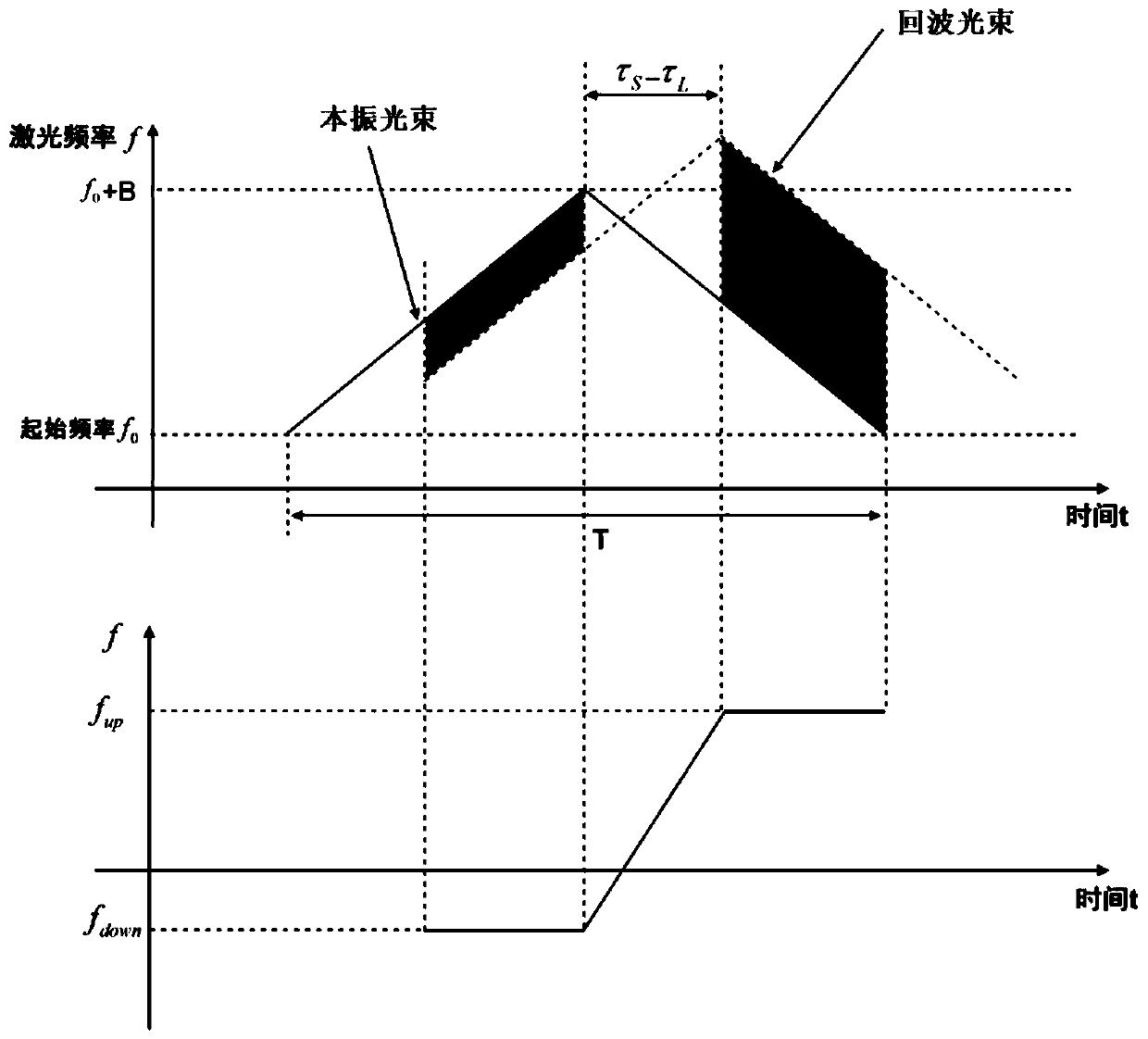
[0003] However, the current chirped FM continuous wave lidar still has the following problems: in order to obtain a larger tuning range and thus a higher range resolution, the pulse repetition frequency (PRF) is severely limited; An unresolved problem that seriously affects the accuracy of speed measurement and ranging; LFM deskewing demodulation requires the echo signal and the local oscillator signal to overlap in the time domain, which determines that it is not suitable for detection within a large dynamic range of ranging
[0012] Wu Jun et al. proposed a dual-frequency, dual-modulation, dual-local-oscillator symmetrical triangular linear frequency modulation coherent range-finding and speed-measuring laser radar system, which expanded the distance range of the symmetrical triangular linear frequency modulation ranging and speed-measuring system, and had a high detection repetition rate (Wu Jun, Hong Guanglie, He Zhiping, Shu Rong, A large-ranging dynamic range high-repetition frequency coherent ranging and speed-measuring lidar (Ⅰ): structure and performance, Journal of Infrared and Millimeter Waves, 2014, Vol.33, No.6, 680-690); theory In general, the ranging dynamic range of the system can be increased by extending the modulation period of the signal, but on the one hand, this method requires a large number of coherent beat frequency data points to be collected for spectrum analysis, and on the other hand, it also requires the modulation time bandwidth of the symmetrical triangular chirp However, it is difficult to realize broadband chirp with high linearity for a long time, which greatly increases the complexity of the system and affects the application prospect

Method used


Image

  • Multi-channel high-repetition-frequency large-dynamic-range distance and speed measurement laser radar method and device
  • Multi-channel high-repetition-frequency large-dynamic-range distance and speed measurement laser radar method and device
  • Multi-channel high-repetition-frequency large-dynamic-range distance and speed measurement laser radar method and device

Examples


Embodiment 1

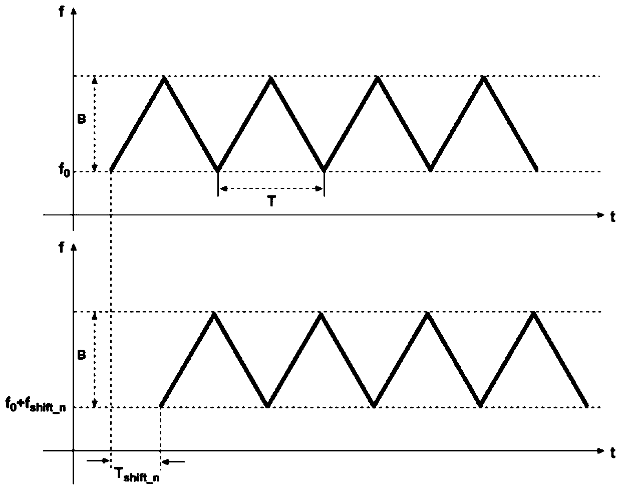
[0079] Example 1: The beam generated by the narrow-linewidth continuous laser source in the radar platform is amplified and then divided into N channels of output beams through a 1×N beam splitter, and the output beams of each channel are respectively passed through a phase modulator and an optical filter to achieve broadband linearity Frequency modulation is used for subsequent speed measurement and distance measurement, where the RF signal source is phase-shifted to drive the phase modulator to achieve different time delays of the output beams of each channel, that is, within a cycle time T, the first output beam does not Delayed emission, the second output beam passes through After a delay of , the third output beam passes through Launch after a delay of ,..., the nth output beam passes through Launch after a delay of , until the last output beam passes through Transmit after a delay; the N delayed output beams are then frequency-shifted by a frequency shifter, and th...

Embodiment 2

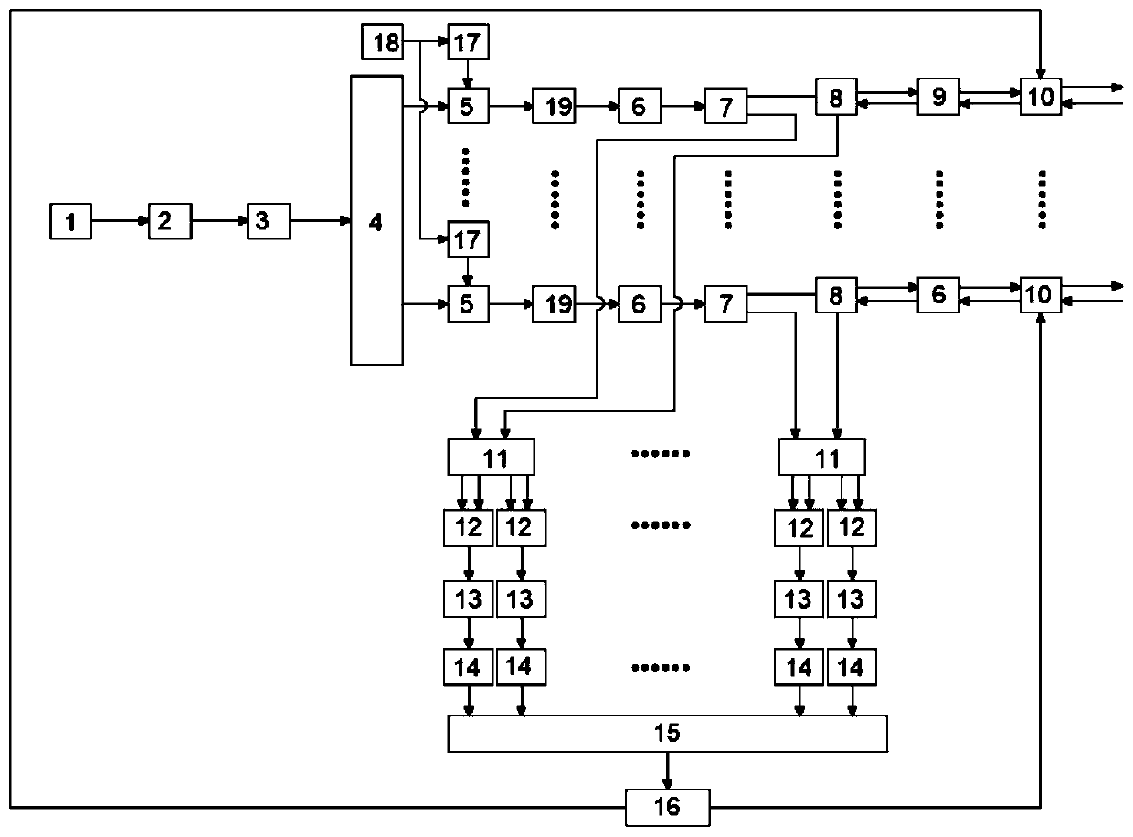
[0081] Embodiment 2: Multi-channel high repetition frequency and large dynamic range distance measurement and speed measurement lidar method, such as figure 1 As shown, including laser light source 1, laser light source 1 adopts eye-safe 1550nm single-mode narrow-linewidth continuous fiber laser, the laser linewidth is 10kHz, the output power is 20mW, the fiber output is protected by isolation, and polarized by polarizer 2, Ensure that the polarization extinction ratio is greater than 25dB, amplify to 600mW through the erbium-doped fiber amplifier 3, and then the polarized light is divided into 2 output beams through the 1×2 beam splitter 4, and each beam passes through the optical fiber phase modulator and optical filter successively, using frequency modulation The frequency modulation signal generated by the signal generator and the mixed frequency signal of the base frequency signal generated by the base frequency signal generator are used as the driving signal of the optica...


PUM


Abstract

The invention discloses a multi-channel high-repetition-frequency large-dynamic-range distance measurement and speed measurement laser radar method and device. A laser light source generates a light beam, the light beam is divided into output light beams of N channels through a beam splitter, broadband linear frequency modulation is carried out on the output light beams of each channel, and then aphase modulator is driven after phase shift of different amplitudes, so that the output light beams of each channel have different time delays; the laser beam is divided into a local oscillation light beam and an emission light beam through a beam splitter; the N transmitting light beams are transmitted to a target in parallel and echo light beams of the target are received, coherent light mixingis carried out on the signals and corresponding local oscillation light beams, intermediate frequency signals containing target distance and speed information are obtained, parallel fast Fourier transform and cross-spectrum processing are carried out on sampling data of the intermediate frequency signals, parallel synchronous measurement of the target distance and speed is achieved, and finally merging output of point cloud images of N channels is achieved through a main control computer. The device can effectively overcome distance measurement ambiguity, and has the advantages of high repetition frequency, large dynamic distance measurement range, high resolution, high precision, high reliability, small size, light weight and the like.

Description

technical field [0001] The invention relates to the technical field of laser radar, in particular to a multi-channel high repetition frequency large dynamic range ranging and speed measuring laser radar method and device. Background technique [0002] Frequency modulated continuous wave lidar combines frequency modulated continuous wave ranging and laser detection technology in modern radar technology. This technology linearly changes the frequency of the transmitted signal in time, and measures the instantaneous frequency of the beat signal between the echo signal and the local oscillator signal to obtain target distance information and radial velocity information. Compared with pulsed laser radar, frequency modulation continuous wave laser radar has the advantages of synchronous ranging and speed measurement, large ranging / speed measuring range, high resolution, multi-target detection and target imaging, etc. field has been widely used. [0003] However, the current chir...

Claims


Application Information

Patent Timeline
Patent Type & Authority Applications(China)
IPC IPC(8): G01S7/481G01S17/58
CPCG01S7/481G01S17/58
Inventor 职亚楠孙建锋潘卫清戴恩文
Owner 孙建锋
Learn More